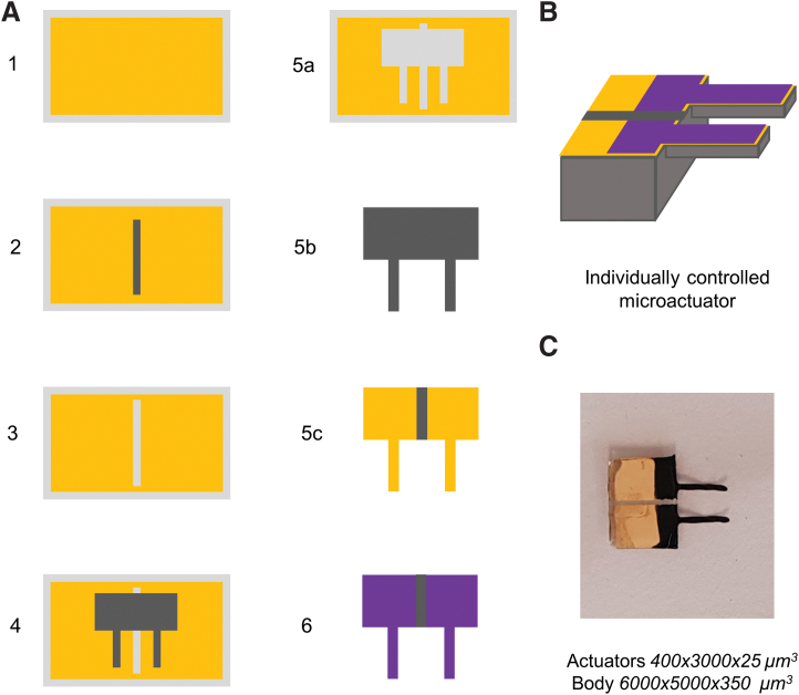
FIG. 7.
(A) Schematic diagram showing the process flow to fabricate individually controlled microactuators: (1) evaporate Au on glass slide; (2) print the pattern layer; (3) remove pattern layer with lift-up to leave patterned Au-coated substrate; (4) print the complete structural layer; (5a) remove the structure with lift-up; (5b) the structure after removal from top side; (5c) the structure from bottom side; and (6) electropolymerize to deposit polypyrrole forming the microactuator device. (B) 3D sketch of the individually controlled microactuator. (C) Individually controlled microactuator fabricated using patterning by printing. Color images are available online.

