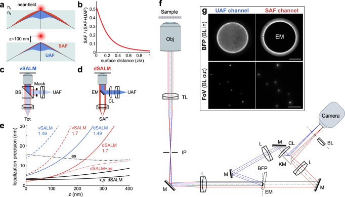
Fig. 1. Concept of supercritical angle localization microscopy (SALM).
a Supercritical angle fluorescence (SAF) occurs when a fluorophore is close to a water-glass interface. b SAF depends strongly on the fluorophore’s z position. c Virtual SALM (vSALM) splits the emission into two equal parts with a beam splitter (BS) and blocks out SAF with a mask in one channel. The z position of the fluorophore is calculated from the ratio of total fluorescence to undercritical angle fluorescence (UAF). d Direct SALM (dSALM) splits SAF and UAF with an elliptical mirror (EM). An additional cylindrical lens (CL) in the UAF channel introduces weak astigmatism (as). e Theoretical localization precision in the axial direction calculated for an NA 1.49 objective in the vSALM configuration as used in refs. 14,15 (blue dashed line) and in the dSALM configuration (blue line), and for an NA 1.70 objective for vSALM (dashed red line) and dSALM (red line), astigmatism (black dotted line) and weighted average of dSALM and astigmatism (red dotted line). The solid black line indicates the lateral localization precision of dSALM (NA 1.70) in x and y, respectively. Calculations are based on experimentally derived PSFs (except dSALM 1.49, which is based on a theoretical PSF model) and assume 5000 photons detected in the UAF channel, and a background of 50 photons per pixel in the UAF channel and five photons in the SAF channel. f Beam path for the dSALM implementation splitting SAF (red beam) and UAF (blue beam) before forming images of the sample on the camera. BFP back focal plane, BL Bertrand lens, CL cylindrical lens, EM elliptical mirror, IP image plane, KM knife-edge prism mirror, L lens, M mirror, Obj objective, TL tube lens. g UAF and SAF channels as seen on the camera with the Bertrand lens (BL) inserted in the beam path (upper panel) or without (lower panel). Scale bars are 2 mm (upper panel) and 5 µm (lower panel). Source Data are available as a Source Data file for Fig. 1e.

