

Abstract
The nucleus pulposus (NP) in the intervertebral disc (IVD) depends on diffusive fluid transport for nutrients through the cartilage endplate (CEP). Disruption in fluid exchange of the NP is considered a cause of IVD degeneration. Furthermore, CEP calcification and sclerosis are hypothesized to restrict fluid flow between the NP and CEP by decreasing permeability and porosity of the CEP matrix. We performed a finite element analysis of an L3-4 lumbar functional spine unit with poro-elastic constitutive equations. The aim of the study was to predict changes in the solid and fluid parameters of the IVD and CEP under structural changes in CEP. A compressive load of 500N was applied followed by a 10Nm moment in extension, flexion, lateral bending, and axial rotation to the L3-4 model with fully saturated IVD, CEP, and cancellous bone. A healthy case of L3-4 physiology was then compared to two cases of CEP sclerosis: a calcified cartilage endplate and a fluid constricted sclerotic cartilage endplate. Predicted NP fluid velocity increased for the calcified CEP and decreased for the calcified + less permeable CEP. Decreased NP fluid velocity was prominent in the axial direction through the CEP due to a less permeable path available for fluid flux. Fluid pressure and maximum principal stress in the NP were predicted to increase in both cases of CEP sclerosis compared to the healthy case. The porous medium predictions of this analysis agree with the hypothesis that CEP sclerosis decreases fluid flow out of the NP, builds up fluid pressure in the NP, and increases the stress concentrations in the NP solid matrix.
Keywords: cartilage endplate sclerosis, disc degeneration, finite element analysis, fluid velocity, fluid pressure
1. Introduction
Low back pain is the leading cause of disability worldwide with 9% of the global population suffering some form of debilitation (Vos et al. 2012). Intervertebral disc degeneration (IDD) is a significant risk factor of low back pain, and one of the causes of IDD is alterations in nutrient fluid supply to the intervertebral disc (IVD) (Urban and Roberts 2003). The IVD is composed of two distinct structures: the nucleus pulposus (NP), an avascular fluid filled structure in the center and the annulus fibrosus (AF), which surrounds it with fiber reinforced rings. Nutrient transport in the NP depends on diffusive fluid flow via the neighboring blood supply from the cartilage endplate (CEP) and the AF (Roberts et al. 1996). The CEP controls the flow of solutes based on pore size and permeability (Rodriguez et al. 2011). Any restrictions in fluid flow between the CEP and the NP results in loss of nutrient flow to the NP and is a causative factor for IDD (Ferguson et al. 2004; Urban et al. 2004). At the cellular level, loss of nutritional fluid inflow and metabolic waste outflow can create a low glucose and acidic environment for NP cells, thereby decreasing cell viability and extracellular matrix (ECM) production (Horner and Urban 2001). Additionally, the CEP undergoes structural changes due to age and trauma (Wang et al. 2012), which disrupts uniform vertebral stress distributions in the IVD and further inhibits cellular metabolism (Lotz and Chin 2000). Modic changes that represent endplate sclerosis have also been reported (Xu et al. 2016). Since the CEP is a fluid flow interface to the NP, it is clinically important to quantify changes in the solid and fluid mechanics in the IVD in response to CEP sclerosis.
Non-invasive in vivo investigation of endplate functional conditions and diffusive capability has been performed in animal models using dynamic contrast-enhanced MRI (Li et al. 2017). Specifically, using an unstable lumbar spine rodent model, CEP sclerosis and decreased IVD height were observed (Bian et al. 2016). As well, increased incidence of endplate sclerosis following discectomy (Grunert et al. 2017) and endplate ischemia (Yuan et al. 2015) have been reported in canine and murine studies, respectively. Finally, decreased blood supply to the endplate led to decreases in IVD height and collagen type II content, as well as NP cell transformation to fibrocartilaginous cells in an ischemic rat endplate model (Yuan et al. 2015). Together, these studies establish the relationship between CEP sclerosis and IDD in animal models under mechanical instability and decreased fluid flow between the CEP and IVD. In vivo clinical measurement of changes in IVD fluid flow under CEP sclerosis is a difficult task and no such study has yet to be reported. Ex vivo pressure sensor measurement of IVD under load is possible but cannot differentiate between fluid pressure and solid stress. Therefore, pressure sensor measurement is insufficient to quantify the changes in NP fluid pressure after CEP structural changes (Velísková et al. 2018). The alternative modality of finite element analysis (FEA) is the best surrogate to predict fluid flow and stress changes in the IVD under CEP sclerosis.
Finite element (FE) models can provide estimates of stress and fluid flow inside the IVD in normal and degenerative cases. FE modelling of a spine functional unit (FSU) is a non-trivial problem because of the non-linear geometry and biphasic material properties of soft tissues (Dreischarf et al. 2014; Galbusera et al. 2011). Previous FE studies have evaluated the effects of CEP structural properties on fluid flow in the IVD. FEA of IVD with CEP found direction-dependent resistance to flow in a constricted poro-elastic model of CEP sclerosis (Ayotte et al. 2000). The resistance to exudation flow was predicted to be higher than imbibition as the constriction radius increased in the CEP. Previous studies on CEP sclerosis have predicted the fluid response in the IVD under axial compression simulating body weight (Ayotte et al. 2000; Ruiz Wills et al. 2018). The spine, however, also undergoes bending loads and complete analysis of CEP sclerosis must include loading moments to simulate daily bending activities. Malandrino et al. performed a statistical factorial study of FSU tissue permeabilities under compression followed by flexion and axial rotation (Malandrino et al. 2009). In this study, a poro-elastic FE model of L3-4 lumbar FSU was developed. The model was used to analyze fluid flow and stress concentrations in the NP and AF under CEP sclerosis and constriction under a compressive pre-load and four types of bending motions: extension, flexion, lateral bending, and axial rotation. It was hypothesized that in response to CEP degeneration, the NP stress and fluid velocity would decrease, while these parameters would increase in the AF.
2. Methods:
2.1. Finite element model development
An FE model of an L3-L4 spine functional unit was developed using the multiple blocks method (Erbulut et al. 2015). The 3D geometry of L3 and L4 vertebrae was obtained from a deidentified computed tomography (CT) scan of a 47-year old healthy male at 0.625 mm slice resolution. The slices were segmented using Mimics® (Materialise Inc., MI, USA) and contrast masks were applied to differentiate between bone and soft tissues. L3-4 IVD geometry was approximated by filling the space between the endplates of L3 and L4 vertebra (Fig. 1a). 3D surfaces were imported in IA-FEMesh (MIMIX, IA, USA) in STL format for block and seed assignment. Separate blocks were assigned to the vertebral body and posterior processes of the vertebra, and were later consolidated for a continuous, 8-node hexahedral mesh (Fig. 1b).
Fig. 1:

(A) L3-4 lumbar spine 3D surface geometry was extracted from a healthy human male CT scans and meshed to obtain hexahedral mesh. Ligaments were added using truss elements. (B) Sagittal cross-section of L3-4 spine shows an internal structure including cartilage endplate and nucleus pulposus.
Vertebrae and disc meshes were imported to Abaqus (v2016, Dassault Systemes, RI, USA). The 8-node hexahedral mesh elements were upgraded to 20-node elements. Cancellous bone, AF, CEP, and bone endplate (BEP) were modeled as solid-fluid stress elements (C3D20P), NP as hybrid solid-fluid stress elements (C3D20PH), and cortical bone as solid stress elements (C3D20). Ligaments were modeled as hypo-elastic 2D truss elements (T3D2) to transfer load axially. Facet joints were simulated with surface-to-surface contact with exponential overclosure: clearance of 1.5mm and over-closure pressure of 300MPa were chosen based on our previous analysis using unidirectional GAP elements (Hassan et al. 2017). Poro-elastic material properties were assigned to NP, AF, CEP, BEP, and cancellous bone (Table 1). BEP permeability was assumed a degree higher than the CEP permeability (Rodriguez et al. 2011). AF fibers were modeled as elastic rebar elements aligned 30° and 150° to the transverse plane, with no compression. Cortical bone in the vertebral body and posterior process was modelled as non-porous material. Material properties were based on literature values (Erbulut et al. 2015; Kiapour et al. 2012; Rodriguez et al. 2011).
Table 1:
Material properties of the L3-4 spine functional unit. (E: Young’s modulus; v: Poisson’s ratio; Es: solid bulk modulus; Ef: fluid bulk modulus). The values were obtained from literature and previous lab studies (*Erbulut et al. 2015; #Kiapour et al. 2012; ‡Galbusera et al. 2011; †Malandrino et al. 2009). Bone endplate permeability was assumed a degree higher than cartilage endplate to differentiate in flow resistance between cartilage-bone enplates (Rodriguez et al. 2011).
| Section | Mechanical Parameters E (MPa), v | Porous Modulus | Void Ratio (e) | Permeability (mm4/Ns) | |
|---|---|---|---|---|---|
| Es (MPa) | Ef (MPa) | ||||
| Cortical Bone | 12000, 0.3*# | - | - | - | - |
| Posterior Bone | 2500, 0.3 | - | - | - | - |
| Cancellous Bone | 100, 0.2# | 10,000 | 2300 | 1 | 20 |
| Bone Endplate | 4000, 0.3 | 5000 | 0.8 | 7.5×10⁻² | |
| Cartilage Endplate | 5, 0.17† | 1000 | 1.5 | 7.5×10⁻³‡ | |
| Nucleus Pulposus | 9, 0.495# | 1000 | 4‡ | 7.5×10⁻⁴‡ | |
| Annulus Fibrosus- Matrix | 2.5, 0.4 | 2000 | 2.33‡ | 7.5×10⁻⁴‡ | |
| Annulus Fibrosus - Fibers | 350–550, 0.3*# | - | - | - | - |
| Ligaments | Hypoelastic*# | ||||
2.2. Constitutive Formulation
Non-porous cortical bone was assigned a linear elastic constitutive equation, which follows Hooke’s law (Equation 1). The effective stress tensor, σij, is dependent on Lame constants (λ,G) and strain tensor, εij. Replacing Lame constants with Young’s modulus, E, and Poisson’s ratio, v, yields Equation 2.
| (Equation 1) |
| (Equation 2) |
IVD, endplates, and trabecular bone were assigned poro-elastic constitutive formulation (Equation 3). The effective stress tensor of porous medium, σpij, is sum of solid structure stress component and hydrostatic pore fluid pressure. Solid stress tensor follows Hooke’s Law, and fluid stress component is dependent on hydrostatic pressure, p, in principal directions.
| (Equation 3) |
where α is Biot’s coefficient and is defined as Es/H’ (Es: Bulk modulus of drained elastic solid and H’: Poro-elastic expansion coefficient).
Permeability, k, is a function of void ratio, e, as shown in Equation 4:
| (Equation 4) |
where k0 is initial permeability, e0 is initial void ratio, and M is experimentally determined tensor. Void ratio is expressed as follow:
| (Equation 5) |
where n is porosity (fluid volume fraction) of the tissue.
At low fluid velocity in a porous medium, Darcy’s law is applicable which approximates Forchheimer’s Law by setting velocity coefficient as zero. According to Darcy’s law, apparent fluid velocity, v, is defined as:
| (Equation 6) |
where μf: viscosity of fluid and ∇p: change is fluid pressure.
Poro-elastic formulation in Abaqus was used through SOILS (Solid-fluid consolidation) analysis and transient pore fluid response.
2.3. Load, Boundary Conditions, and Degenerated Model
Model validation was performed with a 500 N compressive load, similar to physiological upper body standing weight of 50 kg, applied as a connector force of 250 N each on the left and right sides of the L3 vertebral body. The location of the connector force was chosen to minimize the segmental rotation to 0.2° (Panjabi 2007). The load was applied at 500N/s and held for 15mins to analyze creep response. The compressive pre-load was followed by a physiological pure moment of 10Nm, as used in previous cadaver and FE studies (Erbulut et al. 2015; Yamamoto et al. 1989), in three rotational motion directions: extension/flexion, lateral bending, and axial rotation. Compression was applied at 500N/s and pure moment was applied at 10Nm/s to simulate instantaneous loading. Two degenerated cases were simulated by changing the structural material properties of the CEP. Young’s modulus of CEP was increased from 5 MPa (healthy) to 3.5 GPa (calcified), similar to the Young’s modulus of cortical bone endplate (Galbusera et al. 2011) and the CEP matrix porosity was decreased from 60% to 10%. In the first degenerated case, Calcified CEP (CC), permeability was decreased from 7.5×10⁻³ to 7.5×10⁻⁴ mm4 N−1 s−1 to simulate increasing resistance to fluid flow (Guo et al. 2016). In the second degenerated case, Constricted Sclerotic CEP (CS), permeability was decreased 100 times from 7.5×10⁻³ to 7.5×10⁻⁵ mm4 N−1 s−1 to simulate constricted fluid flow along with sclerosis. For the CS case, the permeability is 100 times lower than the healthy case and, therefore, can be assumed as a CEP with a blocked fluid flow path (Guo et al. 2016). The degenerated models were all evaluated under a 500N compressive pre-load followed by 10 Nm moment on extension, flexion, lateral bending, and axial rotation. The lower endplate of the L4 vertebra was fixed in all directions. The outer boundary of the AF was assigned zero pore pressure to simulate a free boundary for fluid drainage. Maximum principal stress, von Mises stress, pore fluid pressure, and fluid velocity were estimated for the NP, inner and outer AF, and CEP under load.
3. Results:
3.1. Validation
The L3-4 FE model was validated for intradiscal pressure (IDP) and disc height under 500N of compressive load with 15mins of creep to simulate physiological loading. Fig. 2 shows the creep response of the IDP and disc height, which was in range of experimental IDP values reported in the literature under the same loading conditions (Heuer et al. 2007). The maximum predicted IDP was 0.56 MPa, which decreased exponentially to 0.30 MPa after 15 mins. This is consistent with Heuer et al., who reported average IDP of 0.49 MPa (range: 0.36–0.53 MPa) which decreased linearly to 0.48 MPa (range: 0.36–0.52 MPa). Average predicted IDP in our FEA was 0.34 MPa at the start of creep and decreased exponentially to 0.17 MPa after one-third of the time. Height reduction of the cranial IVD surface was predicted and normalized with respect to the caudal IVD surface for the start of the creep step. Total height reduction of 0.15 mm was predicted at the end of 15 mins. This was similar to height reduction reported by Heuer et al. who showed median height reduction of 0.16 mm during the creep phase.
Fig. 2:

(A) Intradiscal pressure (IDP) and (B) loss in height of L3-4 lumbar spine under 500 N of compression. The load was applied in 1 s and held for 15 mins for creep response. Maximum predicted pressure was 0.56 MPa, which decreased to 0.30 MPa after creep. Loss in IVD height was 0.15 mm at the end of 15 mins creep.
3.2. Maximum principal stress and von Mises stress in NP and CEP increased with calcified CEP conditions
Maximum principal stress (σp) and von Mises stress (σv) were predicted (Fig. 3) in the IVD and CEP. In a healthy condition, σp in NP were predicted as −0.069, 1.272, 1.054, 0.753, and 0.275 MPa in compression and subsequent rotational motions (COMP, EXT, FLEX, LB and AR respectively). These were increased in CC and CS by an average of 157, 180, 189, 191, and 221%. σv in the healthy NP was predicted as 0.557, 1.617, 1.7, 1.512, and 0.948 MPa. σv values were increased by 114, 167, 150, 147, and 175% on average in the CC and CS. There were only minor differences between the CC and CS in the predicted results.
Fig. 3:
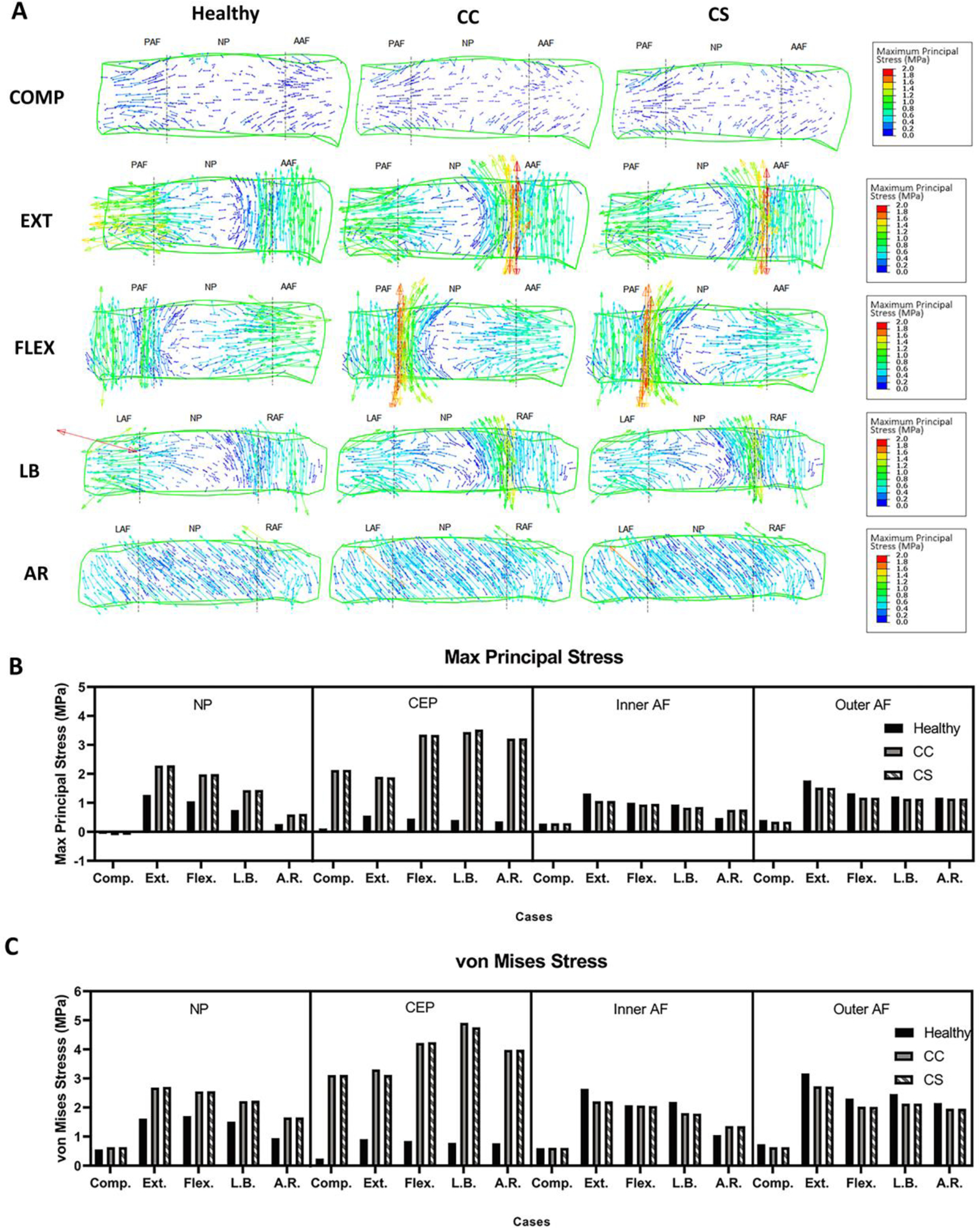
(A) Stress tensor flow maps of the L3-4 disc under compression (COMP), extension (EXT), flexion (FLEX), lateral bending (LB), and axial rotation (AR) for healthy, calcified cartilage (CC), and constricted sclerotic (CS) cases. COMP, EXT, and FLEX are shown in the sagittal view while LB and AR are shown in a coronal view. Predicted (B) maximum principal and (C) von Mises stress in the nucleus pulposus (NP), inner and outer annulus fibrosus (AF), and cartilage endplate (CEP). Both stresses increased in calcified sclerotic cases. (PAF: posterior annulus fibrosus; AAF: anterior annulus fibrosus; LAF: left annulus fibrosus; RAF: right annulus fibrosus; NP: nucleus pulposus).
σp in the healthy CEP was estimated 0.116, 0.559, 0.455, 0.407, and 0.355 MPa in all motions, respectively. In diseased conditions, the average CC and CS were predicted to increase by 1838, 338, 736, 856 and 907% compared to healthy. σv was estimated at 0.241, 0.911, 0.846, 0.784 and 0.767 MPa in the healthy condition and likewise, was increased by an average of 1295, 353, 501, 617, and 519% in the diseased conditions. There was a negligible difference between CC and CS estimations of the magnitude of changes in CEP stresses. In contrast, the calcification of CEP resulted in decreased σv magnitudes in most of inner and outer AF estimations.
3.3. Lower permeability in calcified CEP condition constricted pore maximum fluid velocity in NP and CEP
Maximum fluid velocity (FV) in the healthy NP was predicted as 0.176, 0.69, 0.459, 0.349, and 0.155 μm/s in compression and subsequent rotational motions. FV in CC was estimated to increase by 182, 158, 224, 234, and 321% for the healthy condition, while FV in CS was estimated at 80, 61, 76, 84, and 143% of healthy values, showing a trend of lower magnitudes except in AR. FV in the healthy CEP was estimated as 6.944, 26.535, 22.697, 20.917 and 6.042 μm/s. As expected for the lower permeability parameter, FV in CEP of CC was estimated 15, 14, 13, 14, and 23% of the FV of the healthy CEP. The fluid velocity further decreased in magnitude in CS by 2–3% of the healthy FV in the CEP, indicating further constriction of flow in the CEP. Predicted FV in the inner and outer AF ranged from 74% to 163% in CC, and from 76% to 87% in CS, showing reduced FV in the AF in general. Fluid directions in midsection of the IVD are shown in Figure 4. Again, greater magnitudes of FV were predicted in the CC CEP and further constricted in the CS CEP, especially in the region where the compressive load was applied. FV in the NP was estimated to move along the transverse axis, while the loaded zone showed higher movement in the vertical axis. Magnitudes of FV in EXT and FLEX were predicted to be comparatively higher than other rotational motions since the compressive motion was directly applied to IVD. Vertical fluid movement in AR in CC and CS group did not change much, primarily due to circumferential movement of fluid from rotation, where the left and right AF gather fluid movement.
Fig. 4:

(A) Flow maps of the L3-4 disc under compression (COMP), extension (EXT), flexion (FLEX), lateral bending (LB), and axial rotation (AR) for healthy, calcified cartilage (CC), and constricted sclerotic (CS) cases. COMP, EXT, and FLEX are shown in the sagittal view while LB and AR are shown in a coronal view. (B) Maximum predicted fluid velocity in the nucleus pulposus (NP), inner and outer annulus fibrosus (AF), and cartilage endplate (CEP). (PAF: posterior annulus fibrosus; AAF: anterior annulus fibrosus; LAF: left annulus fibrosus; RAF: right annulus fibrosus; NP: nucleus pulposus).
3.4. Increased maximum pore pressure in calcified conditions in rotational motions except in axial rotation
The maximum pore fluid pressure (POR) was predicted in the IVD and CEP (Fig. 5). POR in the healthy NP was predicted as 0.716, 1.712, 1.672, 1.536, and 0.795 MPa in compression and subsequent rotational motions. In the CC group, POR was estimated at 140, 174, 156, 165, and 161% of healthy POR. In the CS group, POR was estimated at 138, 174, 156, 162, and 165% of healthy POR, and not significantly different from the values from POR in the CC. POR in the CEP in the healthy condition was predicted as 0.754, 2.454, 2.09, 1.962, and 0.836 MPa, while POR in the CC CEP was estimated as 108, 102, 105, 102, and 124% of healthy, and POR in the CS CEP was estimated to increase by 126, 125, 120, 122, and 156% of healthy. POR in the CS CEP showed higher magnitudes, reflecting constriction of fluid flow due to lower permeability and leading to higher pore pressure. While POR in the inner AF increased in magnitude from the healthy to the calcified and constricted conditions, POR in the outer AF showed decreased in magnitude after compression and rotational motions. These conflicting results between POR of the inner and outer AF may be associated with the possibility of disc bulging. The pore pressure contour maps of IVD in compression and rotational motions show that where compressive loads were placed resulted in higher POR. Higher magnitudes and larger areas were predicted to be affected from COMP, FLEX, EXT, and LB from healthy to diseased conditions. POR maps of midsection of IVD showed that the more severe the condition, the higher POR and greater affected area were predicted in all cases.
Fig. 5:

(A) Contour plots the L3-4 disc under compression (COMP), extension (EXT), flexion (FLEX), lateral bending (LB), and axial rotation (AR) for healthy, calcified cartilage (CC), and constricted sclerotic (CS) cases. COMP, EXT, and FLEX are shown in the sagittal view while LB and AR are shown in a coronal view. (B) Maximum predicted pore fluid pressure in the nucleus pulposus (NP), inner and outer annulus fibrosus (AF), and cartilage endplate (CEP). Maximum fluid pressure increased in NP and inner AF but decreased in outer AF for all diseased cases. (PAF: posterior annulus fibrosus; AAF: anterior annulus fibrosus; LAF: left annulus fibrosus; RAF: right annulus fibrosus; NP: nucleus pulposus).
3.5. Decreased degree of range of motion was predicted in diseased rotational motions
In EXT, FLEX, LB, and AR, range of motion in the functional spinal unit in L3-L4 was predicted (Fig. 6). Compared to the healthy group, both CC and CS groups showed 11–21% decreases in angular degrees for each rotational motion. However, there were no notable differences between CC and CS in range of motion, showing calcification of CEP may contribute more significantly to the movement of functional spinal units than constriction of fluid in the CEP.
Fig. 6:

Range of motion (ROM) of L3-4 lumbar spine under extension (EXT), flexion (FLEX), lateral bending (LB), and axial rotation (AR) for healthy, calcified cartilage (CC), and constricted sclerotic (CS) cases. ROM decreased for calcified cases compared to healthy.
4. Discussion
A FEA of the L3-4 lumbar FSU was evaluated under poro-elastic constitutive formulation and a physiological compressive load and pure rotation moments. We simulated changes in porosity, permeability, and matrix rigidity in a combined manner because clinically, these changes manifest in a combined manner in CEP sclerosis (Galbusera et al. 2011). The analysis compared two levels of CEP degeneration, including increased calcification, and decreased porosity and permeability. Post-processing of the predicted stress, fluid velocity, and pore fluid pressure in the IVD and CEP showed alterations in the mechanical response of the porous medium due to structural changes in the CEP.
Fluid flow in and out of the IVD provides mechanical stability against compressive forces and nutrients to the avascular NP. The structural parameters of the vertebral endplates have been shown to affect fluid exchange in the IVD, particularly in the NP (Fields et al. 2018). The porosity of the CEP determines the maximum size of the molecules passing through it and, therefore, influences the flow of nutrients to the IVD (Ferguson et al. 2004). CEP sclerosis decreases the pore space due to calcification, decreases fluid permeability due to calcium ions, and hinders fluid exchange. CEP consists of proteoglycans which assist in fluid transport. In case of calcification, the native proteoglycans are replaced with calcified cartilage which does not have high affinity to fluid (Roberts et al. 1996). Our FEA predicted that NP fluid velocity would increase for the CC but decrease for the CS case, indicating that decreased permeability may have increased resistance to fluid flow. This trend was observed for the compressive pre-load and bending moments (Fig. 4) indicating the independence of changes in NP fluid velocity from the loading profiles. A similar trend has been reported in statistical analysis to determine the effect of CEP permeability on the IVD fluid velocity (Malandrino et al. 2009). This computational analysis found that NP and CEP fluid velocity were significantly and directly affected by CEP permeability. Our predicted value for healthy CEP fluid velocity was the same order of magnitude as previously reported FE values (Ferguson et al. 2004). Due to experimental constraints of directly measuring fluid velocity in the CEP and NP of intact FSU under the physiological load conditions, the comparison of the fluid velocity predictions was made with existing FEA values (Ferguson et al. 2004; Malandrino et al. 2009).
Fluid pore pressure in the NP was predicted to increase under increasing sclerotic CEP conditions in our FEA. The increase in fluid pressure is due to the resistance faced by the fluid to diffuse out (exudation) through CEP. At equilibrium, the NP should be close to zero fluid pressure as no net fluid exchange occurs, which is seen in the healthy contour plot under a compressive pre-load. In the presence of a less permeable axial path through the CEP, NP fluid is trapped and slowly seeps out in the transverse direction through the AF. This direction dependent resistance to flow was reported in a previous FEA study where increased resistance in exudation was predicted compared to imbibition (Ayotte et al. 2000). Increased fluid pressure in the NP can lead to posterior outer AF bulging out under increased vertical loading and can cause nerve impingement (Adams et al. 1996; Brinckmann and Grootenboer 1991). Moreover, the CEP can experience more transverse shear and tensile stress in the vicinity of high NP fluid pressure. Applying the bending moment after pre-load pushed high exudation pressure towards the compressed segment of the IVD, as shown in the pore pressure contour plots.
Stress in the NP and CEP increased in both sclerotic CEP cases. In a healthy FSU, hydrostatic pressure of the NP is resisted by the CEP, predominantly as tensile stress and transverse shear (Fields et al. 2018). Our FEA agrees with ex vivo studies and shows the CEP under tensile stress in healthy conditions. This stress was predicted to increase by an order of magnitude for sclerotic calcified CEP. Two possible reasons for the increase in CEP stress are provided here: increase in the Young’s modulus of the CEP matrix and an increase in fluid pressure in the NP. The current FEA did not show considerable changes in the CEP stress for calcified cases. Therefore, the increase in the Young’s modulus resulted in increase in stress concentrations in the CEP. The effective stress in the NP increased after CEP sclerosis due to increases in predicted fluid pressure. As the CEP experiences tensile stress at the NP interface, increases in NP stress contribute to stress concentrations in the CEP.
Lumbar spine ROM is usually affected by degeneration and surgical procedures (such as rigid fixation) in the FSU tissues. Our FEA showed a decrease in rotational motions for both degenerative cases. However, no changes between the 2 degenerative sclerotic cases were observed, which lead to the observation that increases in the CEP Young’s modulus stiffened the spine segment and decreased ROM with no significant contributions from reduced CEP permeability. Gulbasera et al. reported decreases in spine flexibility under 7.5Nm of extension-flexion, with disc degeneration coupled to endplate calcification (Galbusera et al. 2011). Our FEA used a higher moment of 10Nm in all three motion directions and concluded that endplate calcification affects all bending motions.
There are a few limitations in the current study. Material properties of the CEP and IVD play an important role in mechanical analyses of spine functional units. We found a large range in the reported literature values for the CEP porous medium permeability, porosity, Young’s modulus, and Poisson’s ratio (Malandrino et al. 2009). The values chosen to be used in this model were those showing the greatest agreement in the literature. Nevertheless, the use of different material properties might result in different predictions. A cadaver study measuring permeability, porosity, and strength of healthy and sclerotic cartilage endplates followed by FEA could limit the uncertainty in parameter selection. Another limitation is the use of linear elastic instead of hyper-elastic constitutive equations for the solid matrix of the IVD tissue. Future work will involve writing a user material (UMAT) routine for porous hyper-elastic material for the IVD tissues to increase the accuracy of prediction under large deformations. In addition, this study only analyzed static compression, mimicking an average weight human under a standing condition and did not simulate dynamic loading. Future studies will analyze loading at low frequencies (i.e., 1–1.5 Hz) to simulate daily conditions such as walking and running. A comprehensive validation will also be performed with healthy and sclerotic cadavers for stress distributions and rotational motions.
In summary, the effect of CEP calcification and sclerosis on the NP was predicted by simulating a compressive load and rotational moments on a poro-elastic FE model of an L3-4 spinal segment. Loss of CEP permeability predicted a decrease in the fluid flow out of the NP through the CEP. Increases in the Young’s modulus of the CEP solid matrix increased the stress concentration in the CEP. Fluid pressure in the NP increased as the CEP calcified, and its permeability and porosity decreased. These computational predictions support the hypothesis that a sclerotic CEP will result in decreased nutritional fluid in the NP and bulging out of NP through AF under compressive and rotational loads. Lack of nutritional fluid and build-up of waste metabolites may lead to an excessive NP cell apoptosis and a loss of extracellular matrix (Jackson et al. 2011). CEP calcification with constrained flow, therefore, cause NP cell death, loss of NP ECM, and the collapse of IVD leading to decreased height, and hence, leads to IDD.
Supplementary Material
Acknowledgments
This work was kindly supported by the National Institute of Health (NIH) (R01AR52379 and R01AR61821). The authors wish to thank Nicholas van Nest and Michael Stinson for their excellent technical support with the finite element analysis.
Footnotes
Publisher's Disclaimer: This Author Accepted Manuscript is a PDF file of an unedited peer-reviewed manuscript that has been accepted for publication but has not been copyedited or corrected. The official version of record that is published in the journal is kept up to date and so may therefore differ from this version.
References
- Adams M, McNally D, Dolan P (1996) ‘Stress’ distribution inside intervertebral discs J Bone Joint Surg Br 78:965–972 [DOI] [PubMed] [Google Scholar]
- Ayotte DC, Ito K, Perren SM, Tepic S (2000) Direction-dependent constriction flow in a poroelastic solid: the intervertebral disc valve J Biomech Eng 122:587–593 doi: 10.1115/1.1319658 [DOI] [PubMed] [Google Scholar]
- Bian Q et al. (2016) Excessive Activation of TGFβ by Spinal Instability Causes Vertebral Endplate Sclerosis Scientific reports 6:27093–27093 doi: 10.1038/srep27093 [DOI] [PMC free article] [PubMed] [Google Scholar]
- Brinckmann P, Grootenboer H (1991) Change of Disc Height, Radial Disc Bulge, and Intradiscal Pressure From Discectomy An in Vitro Investigation on Human Lumbar Discs Spine 16:641–646 [DOI] [PubMed] [Google Scholar]
- Dreischarf M et al. (2014) Comparison of eight published static finite element models of the intact lumbar spine: predictive power of models improves when combined together Journal of biomechanics 47:1757–1766 [DOI] [PubMed] [Google Scholar]
- Erbulut DU, Zafarparandeh I, Hassan CR, Lazoglu I, Ozer AF (2015) Determination of the biomechanical effect of an interspinous process device on implanted and adjacent lumbar spinal segments using a hybrid testing protocol: a finite-element study Journal of neurosurgery Spine 23:200–208 doi: 10.3171/2014.12.spine14419 [DOI] [PubMed] [Google Scholar]
- Ferguson SJ, Ito K, Nolte L-P (2004) Fluid flow and convective transport of solutes within the intervertebral disc Journal of biomechanics 37:213–221 [DOI] [PubMed] [Google Scholar]
- Fields AJ, Ballatori A, Liebenberg EC, Lotz JC (2018) Contribution of the endplates to disc degeneration Current molecular biology reports 4:151–160 [DOI] [PMC free article] [PubMed] [Google Scholar]
- Galbusera F, Schmidt H, Neidlinger-Wilke C, Gottschalk A, Wilke H-J (2011) The mechanical response of the lumbar spine to different combinations of disc degenerative changes investigated using randomized poroelastic finite element models European Spine Journal 20:563–571 doi: 10.1007/s00586-010-1586-4 [DOI] [PMC free article] [PubMed] [Google Scholar]
- Grunert P, Moriguchi Y, Grossbard BP, Ricart Arbona RJ, Bonassar LJ, Härtl R (2017) Degenerative changes of the canine cervical spine after discectomy procedures, an in vivo study BMC Vet Res 13:193–193 doi: 10.1186/s12917-017-1105-5 [DOI] [PMC free article] [PubMed] [Google Scholar]
- Guo L-X, Li R, Zhang M (2016) Biomechanical and fluid flowing characteristics of intervertebral disc of lumbar spine predicted by poroelastic finite element method Acta Bioeng Biomech 18:19–29 [PubMed] [Google Scholar]
- Hassan CR, Stinson M, von Nest N, Qin YX Stress and pore fluid alteration in degenerated lumbar intervertebral disk: a porous medium finite element study. In: 43rd Northeast Bioengineering Conference, Newark, NJ, 2017. [Google Scholar]
- Heuer F, Schmitt H, Schmidt H, Claes L, Wilke H-J (2007) Creep associated changes in intervertebral disc bulging obtained with a laser scanning device Clinical Biomechanics 22:737–744 [DOI] [PubMed] [Google Scholar]
- Horner HA, Urban JP (2001) 2001 Volvo Award Winner in Basic Science Studies: Effect of nutrient supply on the viability of cells from the nucleus pulposus of the intervertebral disc Spine 26:2543–2549 doi: 10.1097/00007632-200112010-00006 [DOI] [PubMed] [Google Scholar]
- Jackson AR, Huang C-Y, Gu WY (2011) Effect of endplate calcification and mechanical deformation on the distribution of glucose in intervertebral disc: a 3D finite element study Computer methods in biomechanics and biomedical engineering 14:195–204 doi: 10.1080/10255842.2010.535815 [DOI] [PMC free article] [PubMed] [Google Scholar]
- Kiapour A, Ambati D, Hoy RW, Goel VK (2012) Effect of graded facetectomy on biomechanics of Dynesys dynamic stabilization system Spine 37:E581–E589 [DOI] [PubMed] [Google Scholar]
- Li H, Yan J-Z, Chen Y-J, Kang W-B, Huang J-X (2017) Non-invasive quantification of age-related changes in the vertebral endplate in rats using in vivo DCE-MRI J Orthop Surg Res 12:169–169 doi: 10.1186/s13018-017-0669-x [DOI] [PMC free article] [PubMed] [Google Scholar]
- Lotz JC, Chin JR (2000) Intervertebral disc cell death is dependent on the magnitude and duration of spinal loading Spine 25:1477–1483 [DOI] [PubMed] [Google Scholar]
- Malandrino A, Planell JA, Lacroix D (2009) Statistical factorial analysis on the poroelastic material properties sensitivity of the lumbar intervertebral disc under compression, flexion and axial rotation Journal of biomechanics 42:2780–2788 [DOI] [PubMed] [Google Scholar]
- Panjabi MM (2007) Hybrid multidirectional test method to evaluate spinal adjacent-level effects Clinical biomechanics (Bristol, Avon) 22:257–265 doi: 10.1016/j.clinbiomech.2006.08.006 [DOI] [PubMed] [Google Scholar]
- Roberts S, Urban JP, Evans H, Eisenstein SM (1996) Transport properties of the human cartilage endplate in relation to its composition and calcification Spine 21:415–420 [DOI] [PubMed] [Google Scholar]
- Rodriguez AG, Slichter CK, Acosta FL, Rodriguez-Soto AE, Burghardt AJ, Majumdar S, Lotz JC (2011) Human disc nucleus properties and vertebral endplate permeability Spine 36:512–520 doi: 10.1097/BRS.0b013e3181f72b94 [DOI] [PMC free article] [PubMed] [Google Scholar]
- Ruiz Wills C, Foata B, Gonzalez Ballester MA, Karppinen J, Noailly J (2018) Theoretical Explorations Generate New Hypotheses About the Role of the Cartilage Endplate in Early Intervertebral Disk Degeneration Frontiers in physiology 9:1210 doi: 10.3389/fphys.2018.01210 [DOI] [PMC free article] [PubMed] [Google Scholar]
- Urban JP, Smith S, Fairbank JC (2004) Nutrition of the intervertebral disc Spine 29:2700–2709 doi: 10.1097/01.brs.0000146499.97948.52 [DOI] [PubMed] [Google Scholar]
- Urban JPG, Roberts S (2003) Degeneration of the intervertebral disc Arthritis Res Ther 5:120 doi: 10.1186/ar629 [DOI] [PMC free article] [PubMed] [Google Scholar]
- Velísková P, Bashkuev M, Shirazi-Adl A, Schmidt H (2018) Computational study of the role of fluid content and flow on the lumbar disc response in cyclic compression: Replication of in vitro and in vivo conditions Journal of Biomechanics 70:16–25 doi: 10.1016/j.jbiomech.2017.10.032 [DOI] [PubMed] [Google Scholar]
- Vos T et al. (2012) Years lived with disability (YLDs) for 1160 sequelae of 289 diseases and injuries 1990–2010: a systematic analysis for the Global Burden of Disease Study 2010 The Lancet 380:2163–2196 doi: 10.1016/S0140-6736(12)61729-2 [DOI] [PMC free article] [PubMed] [Google Scholar]
- Wang Y, Videman T, Battié MC (2012) Lumbar vertebral endplate lesions: prevalence, classification, and association with age Spine 37:1432–1439 [DOI] [PubMed] [Google Scholar]
- Xu L, Chu B, Feng Y, Xu F, Zou Y-F (2016) Modic changes in lumbar spine: prevalence and distribution patterns of end plate oedema and end plate sclerosis The British journal of radiology 89:20150650. [DOI] [PMC free article] [PubMed] [Google Scholar]
- Yamamoto I, Panjabi MM, Crisco T, Oxland T (1989) Three-dimensional movements of the whole lumbar spine and lumbosacral joint Spine 14:1256–1260 doi: 10.1097/00007632-198911000-00020 [DOI] [PubMed] [Google Scholar]
- Yuan W et al. (2015) Establishment of intervertebral disc degeneration model induced by ischemic sub-endplate in rat tail Spine J 15:1050–1059 doi: 10.1016/j.spinee.2015.01.026 [DOI] [PubMed] [Google Scholar]
Associated Data
This section collects any data citations, data availability statements, or supplementary materials included in this article.