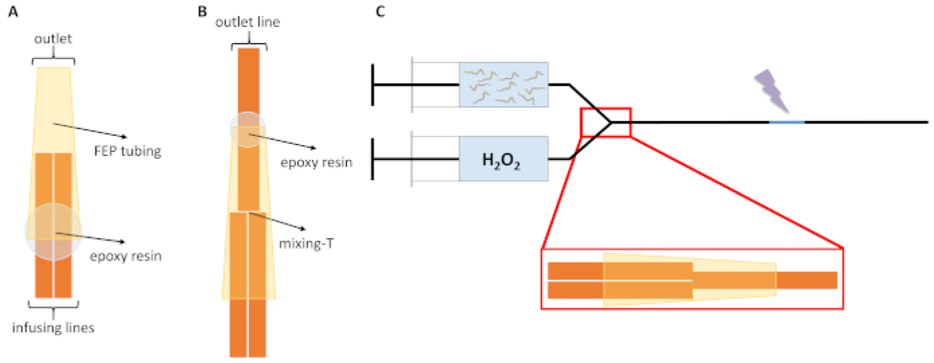
Figure 1. In vivo FPOP microfluidic flow system schematic.

(A) The two infusing lines (orange) of the IV-FPOP flow system are shown inside the FEP tubing (yellow), the correct binding position of the epoxy resin is represented by the light blue circle. (B) Complete assembled mixing-T formed by the three 250 μm i.d. capillaries. The correct resin binding position of the outlet capillary to the FEP tubing is represented by the light blue circle. (C) The complete assembled flow system for in vivo covalent labeling of C. elegans. Prior to FPOP, worms are kept separated from H2O2 until just prior to labeling; the laser irradiation window is shown in light blue and the laser beam is represented by the purple lightning bolt. Figures are not to scale. This figure has been modified from Espino et al.4.
