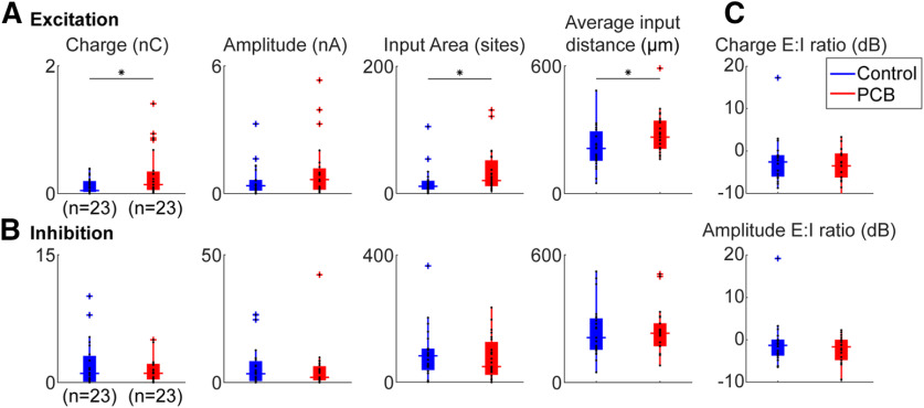
Figure 7.
Comparison of photostimulation-evoked currents between treatments. Comparison of total excitatory (A) and inhibitory (B) input charge, input area, and input distance, between control (blue) and PCB-exposed (red) treated neurons. Boxplots indicate median (horizontal bar), 25th and 75th percentiles (box), range of non-outlier points (vertical whiskers), and outliers (crosses). Black asterisks indicate significant comparisons; *p < 0.05. C, Ratio of excitatory to inhibitory charge between control and PCB-exposed groups.

