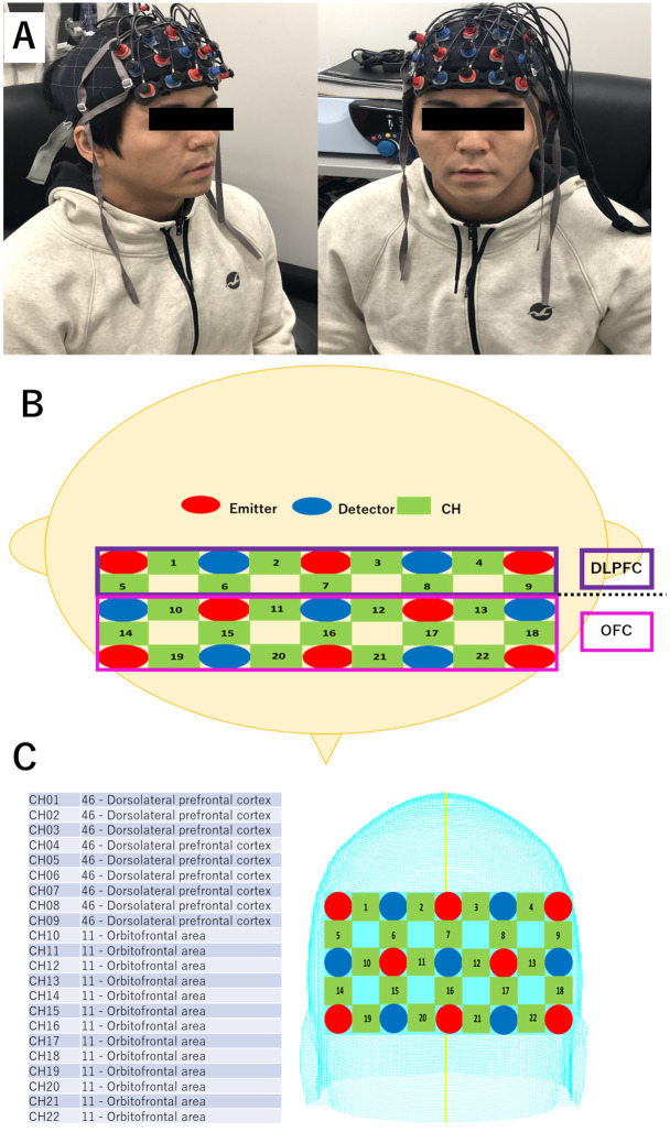
Fig 2. NIRS measurement.
A. A typical picture of a participant equipped with NIRS optodes. B. The NIRS comprised 8 elements for the NIR light emitter (red) and 7 elements for the detector (blue). The numbers indicate the channels (green) recorded. The NIRS channels were placed above the dorsolateral prefrontal cortex (DLPFC) and the orbitofrontal cortex (OFC). C. The channels between the optodes measured on the skull were assigned to the brain regions using the virtual registration method.

