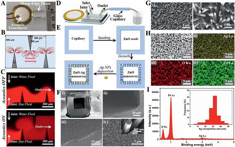
Figure 5.
Acoustofluidic synthesis of functional plasmonic nanoarray inside square-shaped glass capillaries. A) A photograph of an acoustofluidic sharp-edge mixer device with a ruler for scale. B) The design parameters and the proposed acoustic streaming pattern of the sharp-edge micromixer. C) Fluorescent images for comparing the mixing performance of water fluid and dye fluid (Rhodamine B) when the acoustic transducer is OFF (top) and ON (bottom). D) Schematic diagram showing the operation of the acoustofluidic sharp-edge mixer for plasmonic nanoarray synthesis. E) Schematic workflow showing the synthesis process of the plasmonic nanoarray inside the glass capillary. F) SEM images showing the structures of the ZnO nanoarray. The inset in (F-iv) indicates the smooth surface of the ZnO nanorods. G) SEM images showing the structures of the ZnO─Ag nanoarray. H) SEM image (i) and the corresponding element mapping profiles of Ag ii), O iii), and Zn iv). I) EDS spectrum of ZnO─Ag nanoarray, and the inset is the size distributions of Ag from 200 random particles under TEM.

