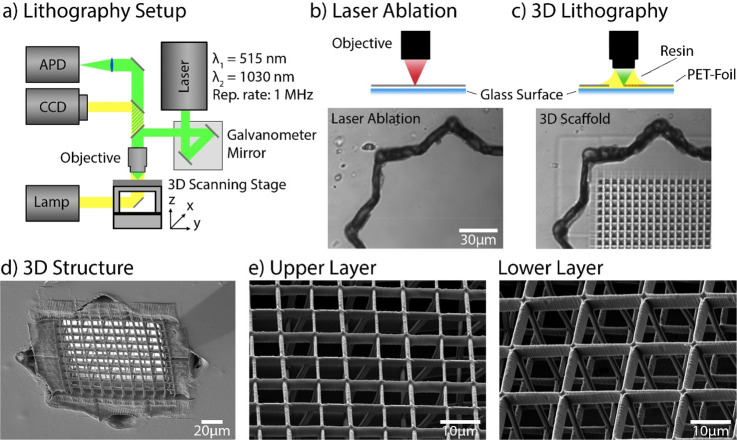
Figure 2.
Modification of the PET foil. (a) Schematic illustration of the MPL setup. A fs-pulsed laser beam was focused through an objective (NA 1.25) in dip-in configuration. Movement of the focal spot within the photoresist was performed via a combination of a galvanometric mirror and a 3-axis stage. Wide-field imaging was used for simultaneous monitoring of the laser processing. The instrument can also be operated in a confocal imaging mode for precise identification of an interface with an APD. (b, c) Schematic illustrations of 3D scaffold fabrication. First, a hole was cut into an impermeable PET foil using laser ablation (1030 nm indicated by red color beam (b)). A bright-field image is shown below. In (c), the hole was covered with the photosensitive resin (yellow drop), and the opening in the foil was closed with a 3D structure using MPL (515 nm indicated by green colored beam). The bright-field image below shows the same position after the hole was filled with a polymer structure. (d) Scanning electron microscopy (SEM) image of the 3D grating inside the foil. (e) SEM image of a grating on the top and bottom side of the foil; the top grid has a mesh size of 6 μm, and the bottom side has a larger (12 μm) mesh size. In addition, the 3D structure axial connectors (30 μm) are observable.

