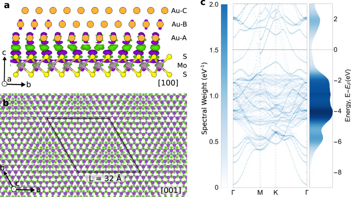
Fig. 5. Electronic structure calculations at the 2D/3D interface.
a Charge density difference viewed down a [100] cross section of the 32 Å commensurate moiré (11Au x 10 superstructure). Orange atoms represent Au, yellow S, and purple Mo. Purple denotes negative and green positive charge density isosurface contours. b Calculated charge density difference at the MoS2/Au{111} interface, as viewed down the [001] axis, showing electronic modulation following the 32 Å moiré periodicity. Black line indicates the 32 Å crystallographic moiré unit cell. c Unfolded band structure for MoS2/Au{111} system (left) and corresponding density of states (right). Color corresponds to the band’s spectral weight.

