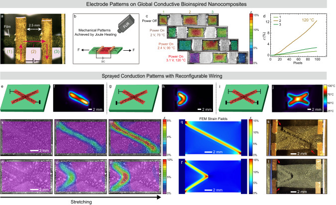
Fig. 4. Electricity-adaptive mechanical patterns under applied voltage.
a–d Mechanical patterns achieved on a global conductive CNF/EG-UPy29/SWNT (50/50/10) nanocomposites by changing the heating zone. a Photograph for the mechanical patterns in CNF/EG-UPy29/SWNT (50/50/10) nanocomposites with copper electrodes. The distance between the copper electrodes is ca. 2.5 mm. The films are divided into three parts, while only the central part undergoes Joule heating. b Illustration of in situ testing setup. c Strain fields just before fracture at different local temperatures in the middle part (with voltage input). d The true strain extracted from DIC at 120 °C in the middle using DIC. The lines 1–3 represent the parts 1–3 in (a). e–t Mechanical patterns achieved via spray patterning conductive SWNT patterns with reconfigurable wiring (process in Supplementary Fig. 10). Illustrations for the films with SWNTs 2D patterns and selectively wiring and the corresponding FLIR images: (e, f) a diagonal, (g, h) an angle, and (i, j) a cross. Strain fields during tensile tests for differently wired patterns by applying voltage on (k–m) a diagonal and (n–p) an angle. The images in each panel are arranged from left to right for increasing global elongation, with the rightmost image just before fracture. Strain fields obtained using COMSOL FEM simulation by applying voltage on (q) a diagonal and (r) an angle. The corresponding crack behavior for the CNF/EG-UPy29 (50/50) films with patterned Joule heating on (s) a diagonal, (t) an angle.

