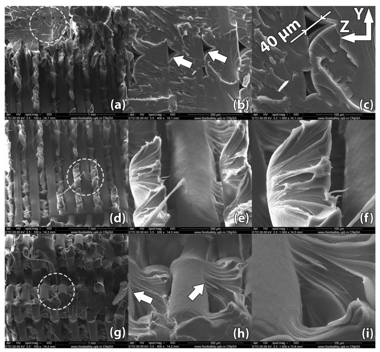
Figure 8.
Scanning Electron Microscopy image of a control sample printed in horizontal orientation (sample #14): (a–c) Due to the raster angle changing from 45° to −45° for each horizontal layer, internal voids 20–50 µm in width remain at the interface of the deposited filaments; (d–f) Upon rupture, the sample presents fracture lines along the deposited layers in a zig-zag pattern specific to the −45°/45° infill used in part manufacturing; (g–i) Interlayer fusion is limited to the areas where the deposited filaments of two horizontal layers intersect.

