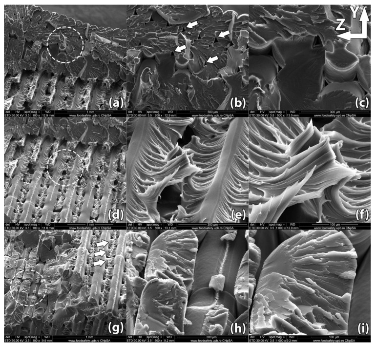
Figure 9.
Scanning Electron Microscopy image of a sample printed in horizontal orientation (sample #05). (a–c) Due to the raster angle changing from 45° to −45° for each horizontal layer, internal voids remain at the interface of the deposited filaments but their size is significantly reduced compared to the control sample, ranging between 15 µm and 30 µm in width; (d–f) Upon rupture, the sample presented fracture lines along the deposited layers in a zig-zag pattern specific to the −45°/45° infill used in part manufacturing; (g–i). Interlayer fusion is increased compared to the control sample.

