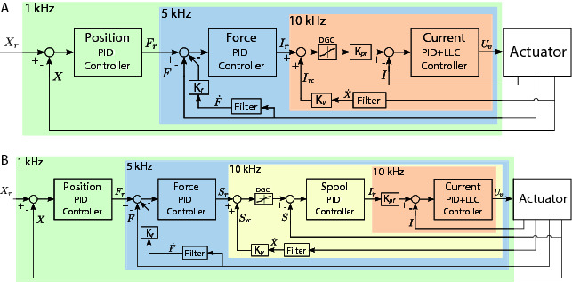
Figure 7.

Control diagram illustrating the arrangement of control blocks for each actuator. (A) Control architecture for the smart manifold mounted on the custom rotary actuator with three nested loops: rotor position control, torque control (at load level using a torque sensor), and the valve current control. (B) Control architecture for the ISA v5 with four nested loops: piston position, force control (at load level using a load cell), spool position control, and valve current control. The control loop frequency selected for each block is indicated on the top-left corner of each respective translucent color box. A velocity compensation term () and a valve current compensation block DGC (due to the valve dual-gain feature) is used in both control architectures. Details on the PID actions and additional terms are described in Section 5.
