Figure 9.

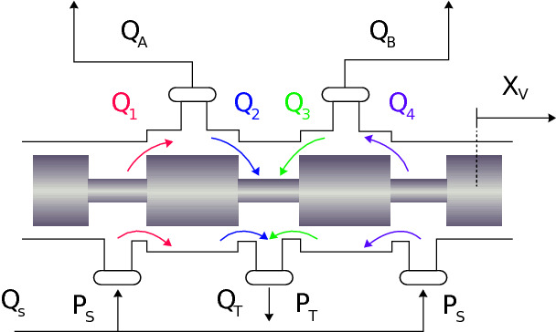
Schematic drawing of a valve that controls the flows and in the actuator chambers. and represent the return and supply pressure, respectively, and are the return and supply flows, respectively, and for are valve port flows.

Schematic drawing of a valve that controls the flows and in the actuator chambers. and represent the return and supply pressure, respectively, and are the return and supply flows, respectively, and for are valve port flows.