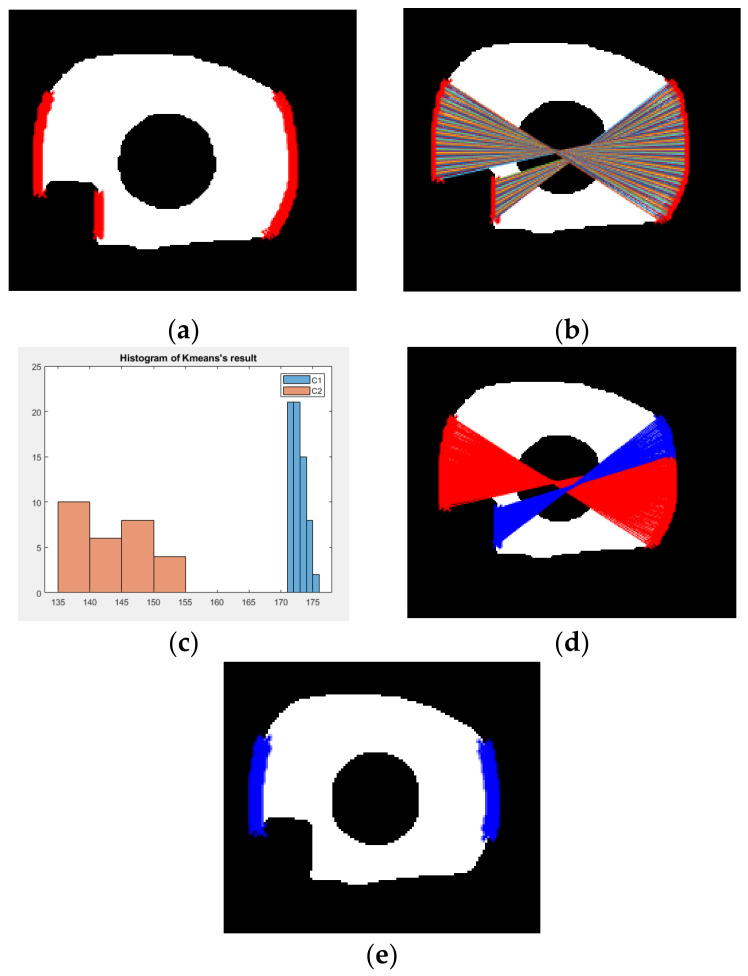
Figure 5.
The illustration of the algorithm “Scan-and-Cluster” to find the saliency points of outer boundary. (a) Red dots denote all boundary points on the left and right side of region of interest (ROI) (within the range between 0.25× and 0.75× height of iris mask region); (b) paired iris points used to compute the distance; (c) histogram distribution of the length of lines; (d) the paired points of two cluster (red lines denote cluster one and blue lines denote cluster two); (e) blue dots denote all recovered saliency points after applying Scan-and-Cluster.

