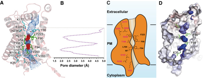
Figure 2. Structure of the central channel in the apo‐PfFNT protomer.

- The central channel in the apo‐PfFNT protomer viewed from the parasite’s membrane plane. The channel, calculated by HOLE (Smart et al, 1996), is indicated by blue dots. The two constriction sites are colored red. Residues forming the constriction sites are in green sticks. Residues that line the rest of the channel are in cyan sticks.
- Representative figure of the calculated diameters of an apo‐PfFNT protomer.
- A cartoon of the central channel formed within a PfFNT protomer. The channel contains two constriction sites in this conformational state. Residues forming these constrictions and the K35‐D103‐N108 and K177‐E229‐N234 triads are illustrated as sticks.
- Surface representation of the inside of the channel formed by a PfFNT protomer (red, negative −15 kT/e; blue, positive +15 kT/e). The five residues K35, F90, F94, K177, and H230, which are subjected for mutagenesis studies, are in green sticks.
