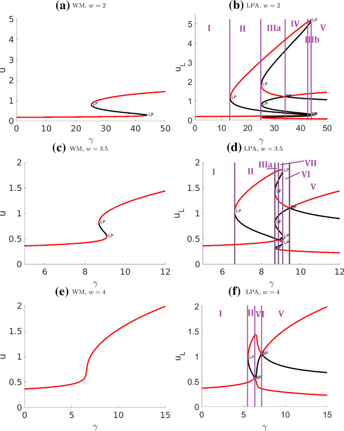
Fig. 4.
Bifurcation diagrams of the well-mixed (WM) and LPA wave pinning system with respect to the rate of activation parameter . Other parameters as in Table 4 (WP) except w. The purple lines are located at bifurcation points separating the distinct regimes. Note that the “global branches” (curves in the WM diagrams) also appear in LPA, though their stability can be different in LPA over certain intervals. The numerical simulation associated with this system is presented in Fig. 9

