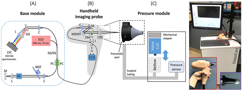
FIGURE 1.
Schematic diagram and photo of the pneumatic OCT system. The system consisted of three parts: A, base module; B, handheld imaging probe; and C, pressure module. Photo on right shows the system with an enlarged view of the handheld probe (see red box). An ear speculum (black) with a standard earbud is visualized in the purple box. C, collimator; CCD, charge-coupled device camera; DC, dispersion compensator; DG, diffraction grating; DM, dichroic mirror; L, lens; LSC, line scanning camera; M, mirror; MEMS, microelectromechanical scanner; NDF, neutral density filter; OBJ, objective; OCT, optical coherence tomography; PC, polarization controller; SLD, superluminescent diode

