
Figure 3.
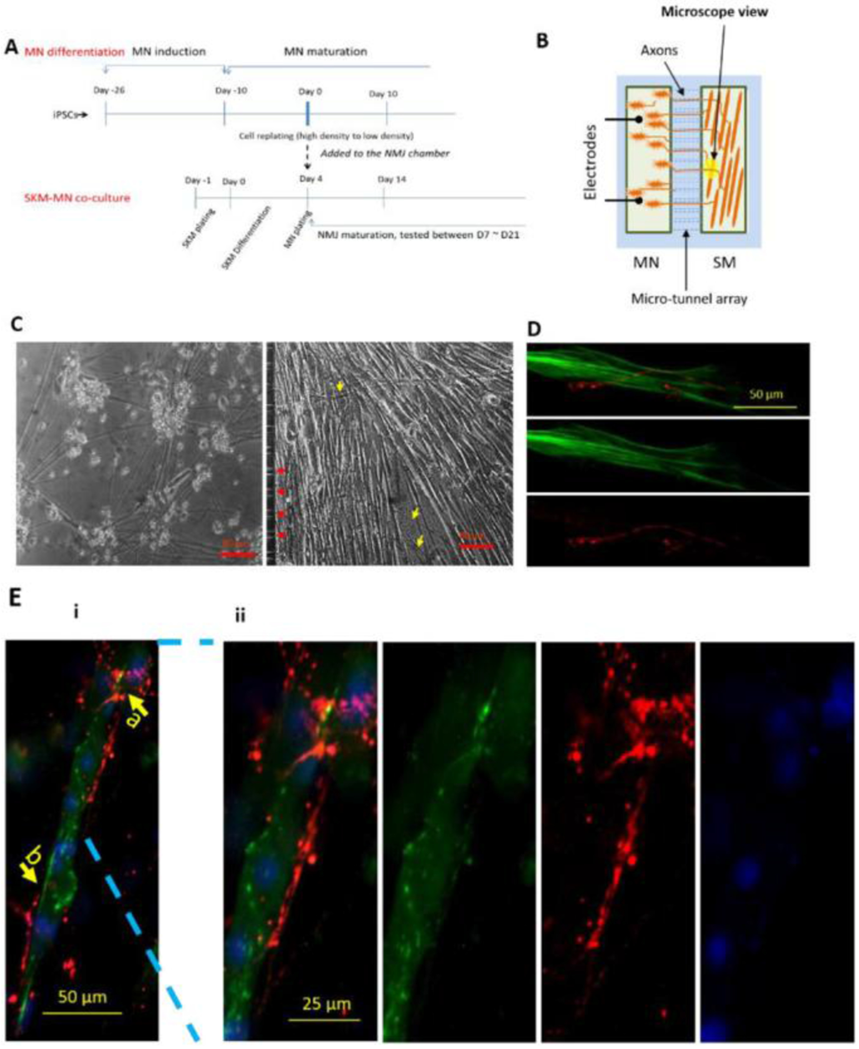
Illustration of the NMJ system. IPSC-MNs were co-cultured separately with WT-SKM where the MN chamber and SKM chamber were connected through micro-tunnels that were axonal permissible, but chemical and electrical impermeable. A) The cell plating scheme for the NMJ cultures inside the micro-chambers. B) Diagram of NMJ chamber system illustrating the MN chamber and SKM chamber are connected via microtunnels, through which MNs sent axons to reach the muscle. MNs were stimulated by field electrodes and induced myofiber contractions were captured by pixel differentials through a phase contrast microscope connected to a video camera. C) Sample phase images of cells in the NMJ system demonstrating MNs in the MN chamber and myofibers in the muscle chamber. Red arrows indicated the tunnel openings for axonal exits and yellow arrows point to some axons in the muscle chamber. D and E) Immunocytochemistry analysis of NMJs in the chambers. D) An image from the muscle chamber indicating an axonal terminal (red, stained with neurofilament) branched at the terminal and wrapped around the myotube which was visualized with the marker myosin heavy chain (MHC, green). Ei) Co-immunostaining with Synaptophysin (red) and Bungarotoxin-488 (green) indicating potential synaptic sites. Arrow b points to a location where the presyanptic terminal is in close alignment with a post-synaptic receptor, while arrow a indicates a close apposition of the two. ii) An enlarged view of i) highlighting the detailed morphology at location a.