
Fig. 1. The formation of reconstructed FCC- versus BCC-like interfacial trilayers at the Ti-segregated WC-Co interfaces on the B and P planes of WC.
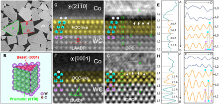
(A) SEM image of a WC-Co composite, where characteristic B and P planes of WC grains are denoted by red and green lines, respectively. (B) Schematic of the WC grain morphology. Pairs of atomic-resolution AC LAADF and iDPC images and line profile analysis (integrated vertically along A➔B direction or horizontally along C➔D direction for each layer) of WC-Co interfaces on B (C to E) and P (F to H) facets, respectively. The yellow color is used to highlight the (FCC- or BCC-like) reconstructed interfacial trilayers. The central layer of the reconstructed interfacial trilayers is defined as the L0 layer. The layers at the WC side are labeled as L, L, etc., while those at the Co side are denoted as L1, L2, etc.