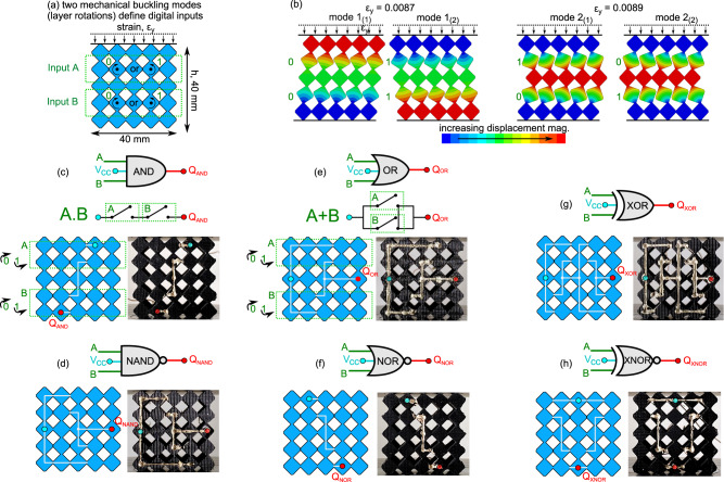
Fig. 4. Formulation of digital logic gates in soft, conductive mechanical metamaterials.
a Schematic of the D1 based metamaterials. Inputs A and B are the rotations in the first and second layers, respectively. b Modal analysis illustrating four possible deformation states. Schematics and experimental images of the Ag-TPU network on the metamaterials for (c) AND, (d) NAND, (e) OR, (f) NOR, (g) XOR, and (h) XNOR logic gates. AND and OR include corresponding switched circuit schematics. Each gate contains two mechanical inputs A and B (green) and one digital output Q (red). The powered input terminal is the cyan node, .

