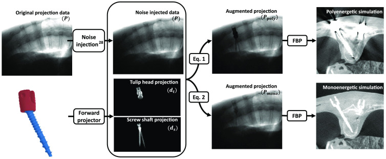
Fig. 5.
Flowchart of the metal simulation process. Original projections were first optionally injected with noise to simulate low tube current projections. Then screws were defined in 3D anatomy and forward projected under the imaging system geometry of the projection images to obtain line-integral distances of the shafts () and tulips heads (). These simulated forward projections were used to augment the metal-free projection data to create metal-injected projections and . The images were then reconstructed with FBP to yield the polyenergetic and monoenergetic reconstructions. The lack of metal artifacts in the monoenergetic model is noteworthy.

