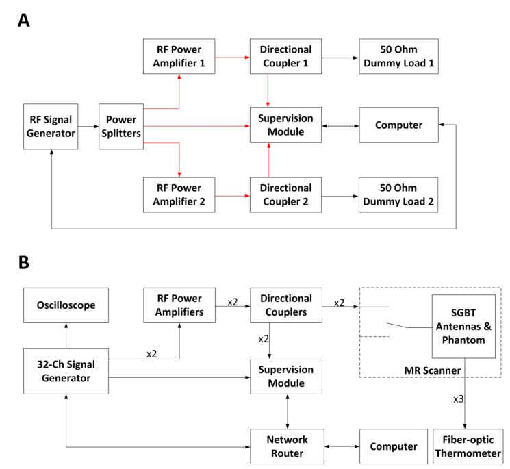
Figure 3.
(A) Schematic of the experimental setup used for the RFPA (RF power amplifier) characterization. The connections illustrated in red share the same cable length. The power splitters and the directional couplers were characterized using a vector network analyzer (ZVT8, R&S) so that the unbalances in the two RF signal chains could be compensated during the characterization of the RFPAs. The computer controls the signal generator via a GPIB (general purpose interface bus) interface. (B) Schematic of the experimental setup in the RF heating experiments. Four coherent RF signals at 400 MHz were generated with a custom-built RF signal generator. One signal was connected to an oscilloscope for monitoring. Two signals were connected to two RFPAs, and the last one was connected to the supervision module as the reference signal. The supervision module monitored and regulated the forward coupled outputs of the directional couplers. The two RF signal chains (from the signal generator to the self-grounded bow-tie (SGBT) antennas) shared the same electrical length. MR: magnetic resonance.

