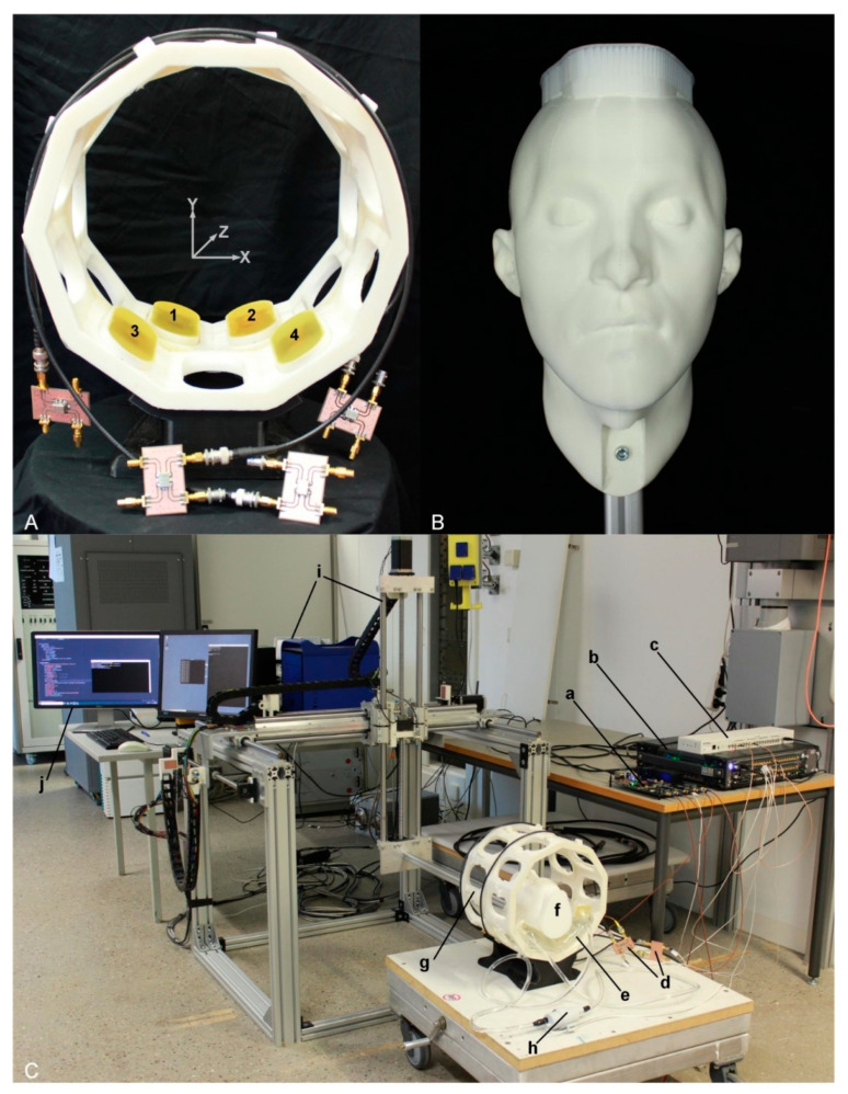
Figure 4.
Experimental setup used for head motion detection. (A) Annular antenna holder in a two-ring arrangement (inner diameter = 24 cm) including ten antenna positions for each ring. Four SGBT antennas (two for each ring) were installed in the holder, as illustrated by the numbers 1–4. The antennas were connected to the signal generator via home-built directional couplers. (B) A 3D printed head model installed to an aluminum profile and used as an object under investigation. (C) The experimental setup, (a) supervision module, (b) custom-built RF signal generator, (c) clock distributor, (d) home-built directional couplers, (e) water pad, (f) head model, (g) antenna holder, (h) water pump, (i) the COSI Measure setup [42], and (j) computer for interacting with the equipment.

