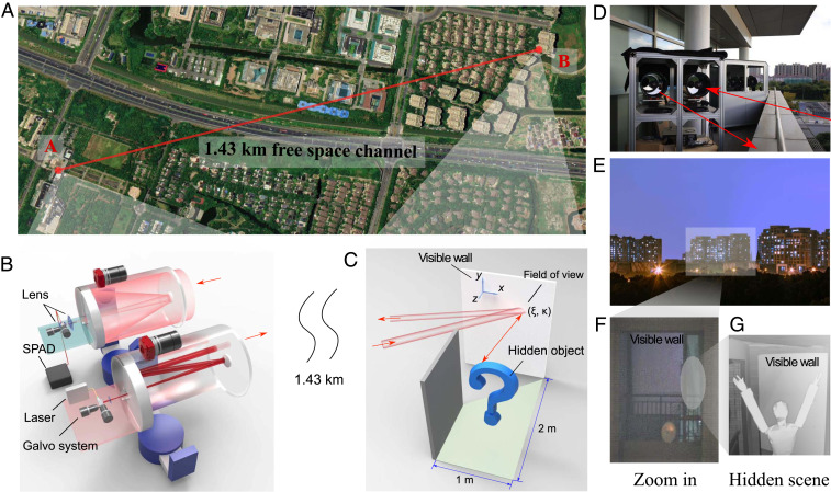
Fig. 1.
Long-range NLOS imaging experiment. (A) An aerial schematic of the NLOS imaging experiment over a (standoff distance of) 1.43-km free-space link, in which the setup is placed at A and the hidden scene is placed at B. (The geographic image is from Google Earth 2020 Google.) (B) The optical setup of the NLOS imaging system, which consists of two synchronized telescopes for transmitter and receiver. A laser followed by galvo system and lenses are used for transmitting light pulses, while an InGaAs/InP SPAD together with a galvo system is used for collecting and detecting photons and recording their TOF information. (C) Schematic of the hidden scene in a room with a dimension size of 2 m1 m. (D) An actual photograph of the NLOS imaging setup. (E and F) Zoomed-out and zoomed-in photographs of the hidden scene taken at location A, where only the visible wall can be seen. (G) Photograph of the hidden object, taken at the room located at B.

