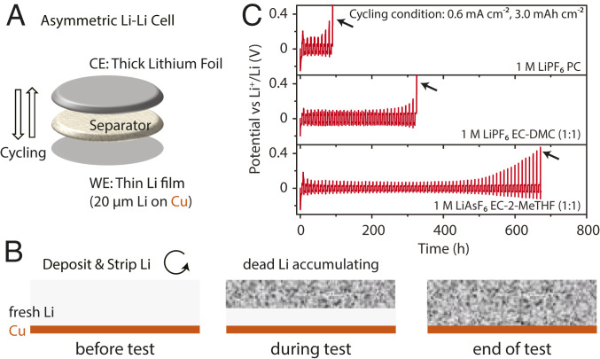
Fig. 4.
Asymmetric Li-Li cell design and test. (A) Schematic illustration of an asymmetric Li-Li cell consisting of a thin Li-metal electrode (working electrode [WE]), a separator, and a thick Li-metal electrode (counter electrode [CE]). In the first half-cycle, a fixed amount of Li is electrochemically deposited onto the thin Li electrode, and then this amount is stripped and deposited repeatedly. (B) Evolution of the Li film on the thin Li electrode (WE) during the test. The Li originally coated on the Cu substrate was gradually consumed by the side reactions, and some of it becomes “dead Li” insulated by a thick SEI layer. (C) Voltage curves of three selected examples of the Li-Li asymmetric cell tests. The cycling current density was 0.6 mA cm−2. The cycling areal capacity is 3.0 mAh cm−2. Li was first deposited on the thin Li electrode and then stripped. The final voltage spikes denoted by the black arrows indicate the end of the tests when there is no Li available for stripping anymore and the absence of short-circuits during the tests. Longer cycle time before the voltage spikes indicate higher CEavg-Li, based on Eq. 4.

