Fig 2.
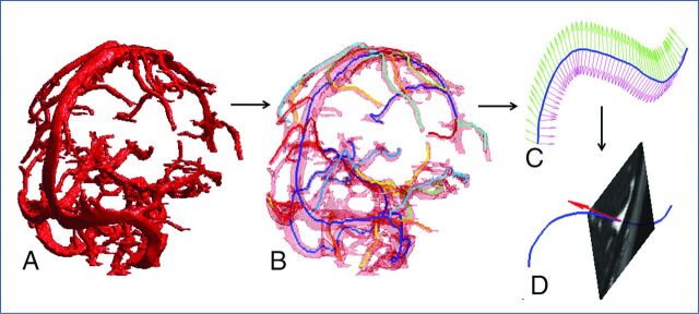
Segmentation and skeletonization. A, Segmented sinus object. B, Superimposition of skeleton branches (shown in different colors) with the segmented vessel object (transparent red). C, Typical definition of the cross-sectional planes for a single skeleton branch (blue line). D, Typical extraction of a cross-sectional plane from image volume.

