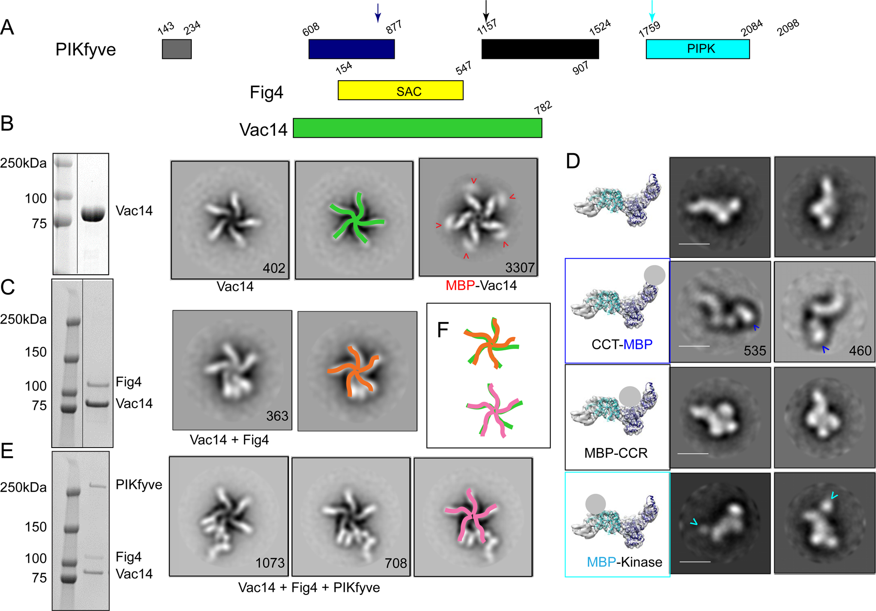
Figure 1. Assembly and gross architecture of the human PIKfyve complex by negative stain EM analysis.

(A) Domain organization of PIKfyve, Fig4, and Vac14. (B) The Vac14 sample used for negative staining EM is pure per SDS-PAGE (line indicates lanes not shown). 2D class averages of Vac14 or MBP-Vac14 show that it pentamerizes. Numbers of particles for each class average are indicated. Maltose binding protein (MBP) fused to the Vac14 N-terminus is at the tip of the Vac14 “leg”. (C) The Fig4/Vac14 sample used for negative staining EM is pure per SDS-PAGE (line indicates lanes not shown). 2D class averages of Fig4/Vac14 show Fig4 between two Vac14 “legs”. (D) Negative stain EM analysis of PIKfyve or MBP+PIKfyve fusions. MBP was inserted into the PIKfyve sequence as indicated by arrows in 1A. The left-most column shows PIKfyve density from the cryo-EM maps (Fig. 2) with docked models of the CCT and kinase modules; a grey ball indicates the location of MBP in the class averages. The other columns show 2D class averages of PIKfyve by itself or with MBP-insertions. (E) The PIKfyve/Fig4/Vac14 sample used for negative staining and cryo-EM is pure per SDS-PAGE. 2D class averages of PIKfyve/Fig4/Vac14 show PIKfyve close to Fig4 at the tip of the Vac14 legs. (F) Schematic overlay of the Vac14 pentamers in Vac14, Fig4/Vac14, and PIKfyve/Fig4/Vac14, showing that the 5-fold symmetry of the Vac14 pentamer is distorted in Fig4/Vac14 and PIKfyve/Fig4/Vac14 complexes.
