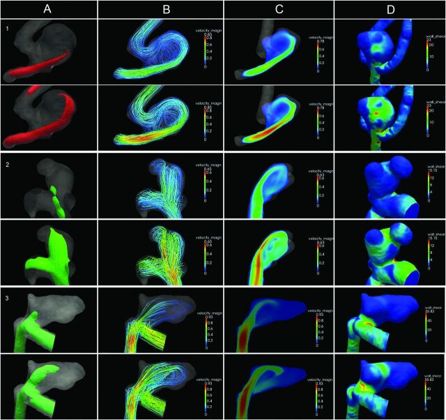
Fig 2.
Intra-aneurysmal hemodynamics in 3 typical aneurysms. Diastole is depicted in the top row; systole, in the bottom row. The columns represent: A, Isosurface of the velocity. B, 3D streamlines colored by velocity magnitude. C, 2D slice of the velocity magnitude. D, Wall shear stress distribution displayed on 3D geometry. The rows represent cases 1–3. Case 1: Ruptured anterior communicating artery aneurysm with a concentrated inflow jet (A and C) and a stable-simple flow pattern: single vortex that is stable throughout the cardiac cycle (B). The impingement zone is located at the body (D). Case 2: Unruptured posterior communicating artery aneurysm with a concentrated inflow jet (A and C) and a stable-complex flow pattern: multiple flow structures that remain stable throughout the cardiac cycle (B). The impingement zone is located at the dome (D) and 2 daughter sacs (D). Case 3: Ruptured anterior communicating artery aneurysm with a concentrated inflow jet (A and C) and an unstable-simple flow pattern: a single flow structure that is unstable throughout the cardiac cycle. The primary direction of flow is different between systole and diastole (B). The impingement zone is located at the neck (D) and 2 daughter sacs (D).

