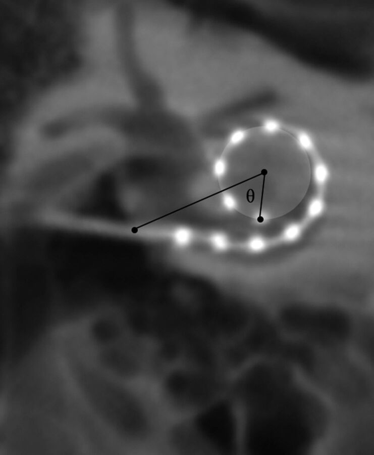
Fig 6.
Method for calculating the angular insertion depth of the most apical electrode. The insertion point, as determined by the axial and sagittal images (not shown) is designated in the coronal oblique image. A circle whose outer circumference represents the trajectory of the 3 most apical electrodes is drawn. A reference line is drawn between the insertion point and the center of this circle. The most apical electrode is then identified and the angle θ is calculated between the electrode and the reference line. In this example, angular insertion depth is calculated by 360 ± θ.

