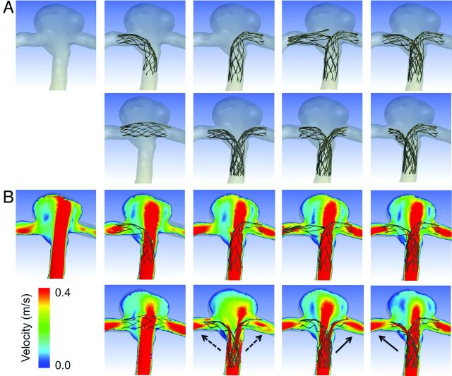
Fig 3.
A, Reconstructed images of 8 different configurations of stent placement and no-stent are shown. The arrangement of panels is the same as in Fig 2. In the first row, from left to right, no-stent, R-stent, L-stent, nonoverlapping-Y, and virtual-Y models are shown. In the second row, from left to right, horizontal, kissing-Y, crossing-Y (R to L), and crossing-Y (L to R) models are shown. B, Contours of flow velocity on a coronal plane at peak systole are shown in the same arrangement as in A. The strongest jet flow into the aneurysm can be seen in no-stent. The jet flow is largely disturbed in the horizontal, kissing-Y, and crossing-Y models. Redirection of flow into the right or the left distal vessel is observed in the kissing-Y (dashed arrows) and crossing-Y (solid arrows) models.

