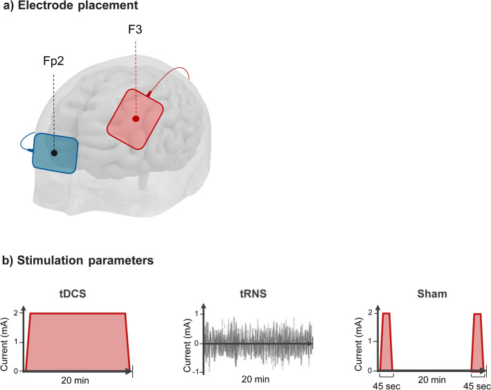
Figure 3.
Electrode placement and stimulation parameters. (a) Electrode placement. 35 cm2 electrodes were used for both anode and cathode. Red dot represents the anode, over the left DLPFC (F3) while the blue dot represents the cathode, over the contra-lateral supra-orbital area (FP2). All stimulation conditions (sham, anodal-tDCS and tRNS) followed the same montage. (b) Stimulation parameters: tDCS for 20 min at 2 mA with a ramp in/out of both 15 s; tRNS current intensity was of 2 mA, with full-spectrum frequency 0.1–600 Hz; sham-tDCS was delivered at the beginning and at the end of 20 min applying 45 s of real stimulation (15 s ramp-up, 15 s stimulation and 15 s ramp-down).

