Abstract
BACKGROUND AND PURPOSE: Previous studies have depicted arterial and aneurysmal anatomy with three-dimensional time-of-flight (3D-TOF) MR angiography before and after treatment with Guglielmi detachable coils (GDCs) and with CT angiography before and after treatment with stents and stent-grafts. We investigated the ability of time-resolved contrast-enhanced 3D MR angiography (3D MR digital subtraction angiography [DSA]) to accurately depict the anatomy of experimental lateral aneurysms before and after treatment with GDCs and a variety of stents or stent-grafts, and compared these findings with 3D-TOF MR angiography without and with contrast enhancement and CT angiography.
METHODS: Two nitinol stents, two nitinol-polytetrafluoroethylene (PTFE) stent-grafts, and two stainless steel stents were deployed in three dogs with experimental carotid aneurysms. In a fourth animal, one of three aneurysms was completely occluded with GDCs. The other two aneurysms were loosely packed to ensure persistence of some residual aneurysmal lumen. Cut-film angiography, CT angiography, 3D-TOF MR angiography without and with contrast enhancement, and 3D MR DSA were performed in all dogs before and 3 weeks after treatment.
RESULTS: 3D MR DSA was superior to conventional 3D-TOF MR angiography without and with contrast enhancement in accurately depicting experimental lateral aneurysms and superior to CT angiography in depicting aneurysms treated by GDCs. 3D MR DSA and CT angiography were comparable in depicting vessels treated with nitinol stents and stent-grafts, whereas CT angiography was superior for showing vessels treated by stainless steel stents.
CONCLUSION: We recommend further development and clinical evaluation of 3D MR DSA for imaging cerebral aneurysms before and after treatment with GDCs. 3D MR DSA or CT angiography may be useful for evaluating vessels containing nitinol stents or nitinol-PTFE stent-grafts, whereas CT angiography should be used for follow-up of vessels treated by stainless steel stents.
Endovascular treatment of cerebral aneurysms continues to evolve rapidly. The Guglielmi detachable coil (GDC) is now widely used, and the effectiveness of a stent to occlude flow across an aneurysmal neck or to constrain GDCs within an aneurysm has been demonstrated experimentally and clinically (1–8). Catheter angiography is performed in accepted protocols for the follow-up of patients with cerebral aneurysms treated by surgery or endovascular therapy (1, 9, 10). The substitution of MR angiography or CT angiography may offer a noninvasive or minimally invasive alternative to conventional catheter angiography, which may result in less patient discomfort and morbidity and greater cost savings (11, 12).
Previous reports have documented the capabilities and limitations of depicting cerebral aneurysms before and after treatment with aneurysm clips (CT angiography and MR angiography) and GDCs (MR angiography) (13–26). Three-dimensional time-of-flight (3D-TOF) MR angiograms may not accurately depict the anatomy of the aneurysms owing to the presence of slow flow and spin saturation, whereas in aneurysms treated with a metallic device, such as a GDC or a stent, artifacts may result from magnetic susceptibility and ferromagnetic and eddy current effects (14, 15, 27–32). Although enhancement with a gadolinium-based contrast agent will improve the visualization of aneurysms containing slow flow on TOF MR angiograms, there is a considerable disadvantage of venous and extravascular enhancement (17, 33). 3D MR DSA reduces spin saturation in regions of slow flow without venous overlap, and thus it may be useful for the more accurate, noninvasive depiction of the morphologic characteristics of aneurysms containing slow flow, which occurs by virtue of aneurysm hemodynamics before and after treatment (34–39). However, vascular MR imaging is expected to be compromised by the presence of metallic endovascular prostheses, such as stents and GDCs. CT has been shown to accurately depict vessels treated with stents and stent-grafts, whereas streak artifacts severely compromises CT scans obtained in the presence of GDCs (40–43). The purpose of this study was to investigate the capabilities of time-resolved contrast-enhanced 3D MR angiography (3D MR digital subtraction angiography [DSA]) to more accurately depict the anatomy of canine experimental lateral aneurysms before and after treatment with GDCs and a variety of stents or stent-grafts, and to compare these results with 3D-TOF MR angiography without and with contrast enhancement and CT angiography.
Methods
Three vein-pouch aneurysms were created on the common carotid arteries in each of four mongrel dogs (two on the right side, one on the left) after a modified method first described by German and Black (44). Treatment of the experimental aneurysms is summarized in Table 1. Stents or stent-grafts were deployed in three animals. Two dogs had a stent placed into one carotid artery and a stent-graft placed into the other; one dog had stents placed into both arteries. The two stent-grafts—nitinol covered with expanded polytetrafluoroethylene (PTFE) (Prograft Medical Inc, Palo Alto, CA)—were placed to completely occlude an aneurysmal ostium. Two uncovered nitinol stents (Prograft) and two stainless steel Palmaz stents (Johnson and Johnson Interventional Systems, Warren, NJ) were deployed so that one of each covered an aneurysmal ostium and the others lay only partially across an aneurysmal ostium (see Table 1). The variable position of the stents relative to the aneurysmal ostium was unintentional, but this did not interfere with the study, as a comparison of the three devices for efficacy of endovascular occlusion was not an objective. Three aneurysms (upper left sides) were untreated. In the fourth animal, one of the three aneurysms was packed as fully as possible with GDCs (Boston Scientific, Natick, MA.) to achieve complete aneurysm obliteration; the other two aneurysms were loosely packed to maintain patency of some residual aneurysmal lumen.
TABLE 1:
Summary of treatment of experimental lateral canine aneurysms

Imaging of the experimental aneurysms is summarized in Table 2. Unenhanced conventional 3D-TOF MR angiography was performed in all dogs only before treatment because of its poor performance in accurately depicting these lateral aneurysms, which contain a large volume of slow flow before treatment. Cut-film angiography, contrast-enhanced conventional 3D-TOF MR angiography, 3D MR DSA, and CT angiography were performed in all dogs before and 3 weeks after treatment. CT angiography was performed using a 1-mm collimation and a 1:1 pitch, a reconstructed slice thickness of 1 mm, 120 kVp, and 220 to 280 mA, unless a large area of coverage was required. In this case, 3-mm collimation, 1.5:1 to 1.9:1 pitch, 220 to 240 mA, and 3-mm reconstructed slice thickness were used (18). Postprocessing was performed on an Advantage Windows Workstation (GE Medical Systems, Waukesha, WI) to produce maximum intensity projection (MIP) images.
TABLE 2:
Methods of imaging used before and after aneurysmal treatment
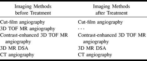
All MR images were acquired on a 1.5-T scanner with fast-gradient capability. The 3D MR DSA images were acquired using a standard dose of 0.1 mmol/kg gadodiamide (Omniscan, Nycomed, Wayne, PA). Scan parameters varied because the technique continued to evolve during the project and scans were tailored to cover the necessary volume of interest in each animal. Representative parameters were as follows: TR/TE = 11.4/2.4, tip angle = 60°, field of view (FOV) = 16 × 8 cm, coronal volume thickness = 32 mm, acquisition matrix = 312 × 128 × 16, and time between temporal acquisition frames = 3.75 seconds. Images were reconstructed using a matrix of 512 × 256 and 32 partitions (34). Pre- and postcontrast 3D-TOF MR angiograms were also obtained with magnetization transfer, flow compensation in all three axes, and variable bandwidths: TR/TE = 33/3.3, tip angle = 25°, partition thickness = 1 mm, axial slab thickness = 64 to 100 mm, FOV = 16 × 12 cm, and matrix = 256 × 144 × 64 (13, 16). Enhanced 3D-TOF MR angiograms were acquired within 10 minutes after bolus administration of gadodiamide for the acquisition of the 3D MR DSA images.
Pre- and posttreatment cut-film angiograms were compared with pre- and posttreatment CT angiograms and MR angiographic source and MIP images to determine the effect of the stents and GDCs on the capability of these techniques to depict the patent lumen of a parent artery or aneurysm. Films were reviewed by two radiologists, and interpretations were reached by consensus.
Results
Conventional 3D-TOF MR angiography did not accurately depict the untreated lateral aneurysms owing to slow flow within them, which leads to spin saturation (Fig 1A and B). Contrast-enhanced 3D-TOF MR angiography only partially offset the vulnerability of TOF MR angiography to saturation artifacts (Fig 1C). In addition, contrast-enhanced TOF MR angiography resulted in increased background signal intensity and venous overlap. 3D MR DSA and CT angiography, performed during contrast infusion, accurately depicted the geometry of the aneurysms and their relationship to the parent artery (Fig 1D and E). Background suppression was superior with 3D MR DSA.
fig 1.
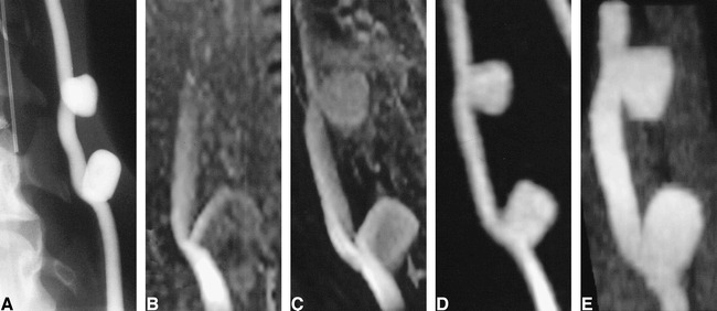
Untreated experimentally induced canine aneurysms.
A, Cut-film subtraction angiogram.
B, Conventional 3D-TOF MR angiogram (33/3.3/1).
C, Contrast-enhanced 3D-TOF MR angiogram (33/3.3/1).
D, 3D MR DSA image (9.3/1.8/1) produced by subtraction of a peak arterial phase 3D image from a baseline 3D mask acquired before the arrival of the intravenous contrast bolus.
E, CT angiogram.
Four aneurysms that were partially or completely covered by the stainless steel or nitinol stents remained patent, and this patency was accurately detected by both CT angiography and MR angiography. Two aneurysms covered by stent-grafts were completely thrombosed (Figs 2–4). Patency of the parent artery was accurately detected proximal and distal to the stent with all four imaging methods, although accuracy of luminal definition at the site of the stent was dependent on the imaging technique and on the composition of the stent (Figs 2–4). Despite the metallic composition of the stents, there were few beam-hardening artifacts on CT scans, although the apparent thickness of the stent on CT scans was dependent on stent composition. The apparent thickness was greatest with the stainless steel stent and least with the nitinol stent. The apparent thickness of the PTFE-nitinol stent-graft was slightly less than that of the stainless steel stent (Fig 5). MIP CT angiograms appeared similar, independent of stent composition (Figs 2B, 3B, and 4B).
fig 2.
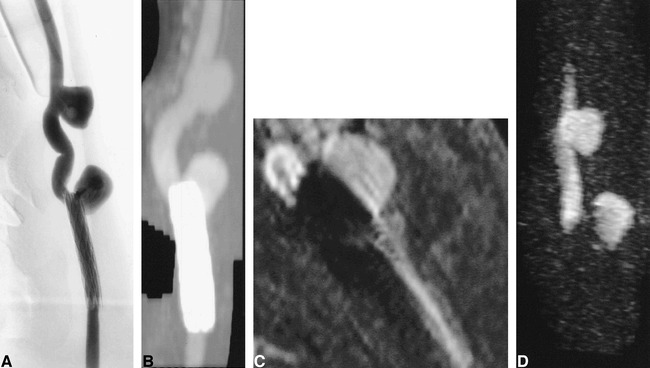
Aneurysm partially treated with a stainless steel stent.
A, Conventional angiogram of stent partially overlying the ostium of a patent aneurysm.
B, CT angiogram.
C, Contrast-enhanced 3D-TOF MR angiographic reformatted planar image (33/3.3/1) parallel to the carotid artery.
D, 3D MR DSA image (11.6/2.4/1). Ferromagnetic artifacts completely suppressed luminal signal intensity on all MR sequences.
fig 5.

CT angiographic source images of aneurysm treated with stents and stent-grafts show differences in artifacts produced by different device compositions.
A, Animal 1. Right (lower aneurysm), stainless steel stent partially herniating into an experimental aneurysm (arrowhead). Left, PTFE/nitinol stent-graft (arrow). The apparent wall thickness of the stainless steel stent on CT is greater than that of the stent-graft because of the high attenuation of the former.
B, Animal 2. Right (lower aneurysm), stainless steel stent (arrowhead). Left, nitinol stent (arrow). The apparent wall thickness of the nitinol stent on CT is less than the stainless steel stent and the PTFE/nitinol stent-graft.
On contrast-enhanced 3D-TOF MR angiography and 3D MR DSA, ferromagnetic artifacts caused by the presence of the stainless steel stent completely obliterated depiction of the blood within the patent artery and signal in the adjacent tissue, although patency of the artery could be inferred from the observation of signal proximal and distal to the stent. The region of signal loss also included the neck of the patent aneurysm, while the signal within the body and fundus of the aneurysm remained intact on contrast-enhanced 3D-TOF MR angiograms and 3D MR DSA images (Fig 2C and D).
The region of signal loss caused by the presence of nitinol was small and was limited to the immediate vicinity of the stents on both contrast-enhanced 3D-TOF MR angiograms and 3D MR DSA images. This allowed fairly accurate depiction of both the artery and patent aneurysm (Fig 3C and D). The presence of the PTFE fabric in the graft material of the stent-graft did not appear to produce any additional artifacts on contrast-enhanced 3D-TOF MR angiograms or 3D MR DSA images (Fig 4C and D).
fig 3.
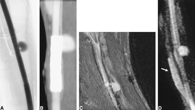
Aneurysm partially treated with a nitinol stent.
A, Conventional angiogram of a nitinol stent overlying the ostium of a patent aneurysm.
B, CT angiogram.
C, Contrast-enhanced 3D-TOF MR angiographic reformatted planar image (33/3.3/1) parallel to the carotid artery.
D, 3D MR DSA image (11.4/2.2/1). Luminal signal intensity in the parent artery and in the region of the aneurysmal neck are visible but some artifacts are present owing to the nitinol stent. Despite dynamic contrast enhancement, some enhancement is seen within the adjacent jugular vein (arrow).
fig 4.
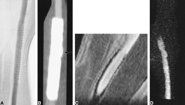
Aneurysm completely treated by placement of a PTFE-nitinol stent-graft.
A, Conventional angiogram.
B, CT angiogram. A small focal luminal protrusion is seen where the stent-graft overlies the ostium of the aneurysm (arrow).
C, Contrast-enhanced reformatted planar image (33/3.3/1) parallel to the carotid artery.
D, 3D MR DSA image (11.6/2.4/1). Luminal signal intensity on MR angiographic sequences is clearly defined despite the presence of the stent-graft.
With 3D MR DSA, definitive evidence of filling of the aneurysms partially treated by GDC embolization was observed (Fig 6A–D). The determination of patency versus thrombosis of partially treated aneurysms using contrast-enhanced 3D-TOF MR angiography was made problematic by the inability to distinguish among contrast-laden flowing blood, enhancing granulation tissue, thrombus, and signal pile-up caused by mild susceptibility artifacts in the region of the coil mass within the aneurysm (Fig 6E–G). Patency or thrombosis of the treated aneurysm could not be assessed on CT scans owing to significant beam-hardening artifacts (Fig 6H).
fig 6.
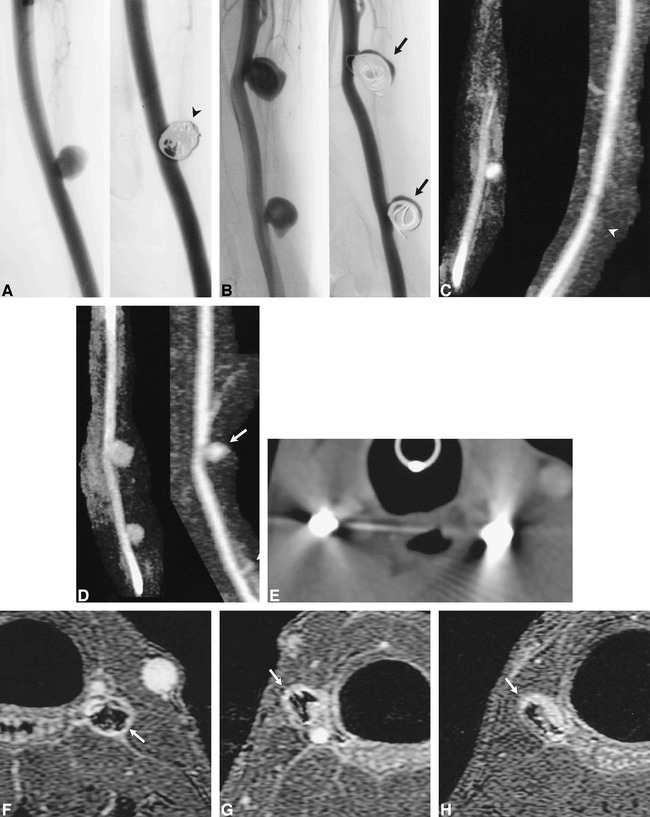
Aneurysms partially and completely treated with GDC embolization.
A and B, Conventional angiograms of left- (A) and right-sided (B) aneurysms before and after GDC embolization. The left-sided aneurysm (arrowhead) was completely treated. The two right-sided aneurysms were partially treated, such that there was persistent flow within the aneurysm (arrows).
C and D, 3D MR DSA images of the left- (C) and right-sided (D) aneurysms before (9.6/2.1/1) and after (11.5/2.3/1) GDC embolization. The left-sided aneurysm is obliterated after treatment (arrowhead). Note the absence of high signal artifacts from thrombosis, soft tissue enhancement, or susceptibility artifacts. Residual flow is accurately depicted in the two right-sided aneurysms, which were partially treated with GDCs (arrows).
E, CT angiographic source image of GDCs. Severe beam-hardening artifact renders these images diagnostically useless.
F, Contrast-enhanced 3D-TOF source image (33/3.3/1) of the left-sided aneurysm completely treated by GDCs. The GDC mass is surrounded by high signal intensity (arrow), which may be the result of flowing blood, thrombus, enhancing granulation tissue, mild susceptibility artifacts, or a combination thereof.
G and H, Contrast-enhanced 3D-TOF source images (33/3.3/1) of incompletely treated carotid aneurysms on lower right (G) and upper right (H) sides. The signal intensity around the coil mass (arrows) is lower than that of the parent artery, although it is similar to that found in the completely treated aneurysm (F). Conventional angiography and 3D MR DSA documented that the two right-sided aneurysms contained flowing blood (C, D).
Discussion
The fidelity of MR angiography in depicting the cerebral vasculature is limited beyond spatial resolution and signal-to-noise ratio by the interaction between flowing blood and the imaging sequence designed to exploit this effect (45). In the intracranial circulation, visualization of small vessels can be improved by the intravenous administration of contrast material before acquisition of a 3D-TOF MR angiogram (17, 33). Areas of interest in the circle of Willis are relatively free of confounding venous overlap on images produced by contrast-enhanced 3D-TOF MR angiography, although there is potential for the presence of venous signal to cause difficulty in image interpretation when the objective is the perception of a small aneurysm or the detail of aneurysmal geometry. This difficulty commonly arises in performing CT angiography for evaluation of middle cerebral artery aneurysms. In addition, the delay in imaging after contrast administration can lead to extravascular enhancement, which may be particularly problematic in determining the incomplete or complete thrombosis of aneurysms treated by endovascular means. Dynamic (first-pass) contrast-enhanced techniques, such as 3D MR DSA, reduce spin saturation while avoiding venous overlap and extravascular enhancement. By producing images with an intrinsically high signal-to-noise ratio and resistance to flow-related artifacts, 3D MR DSA improves image quality in the carotid arteries, aortic arch, and peripheral circulation (34–37). However, these techniques have not found routine clinical application to the circle of Willis, owing to the sacrifice of spatial for temporal resolution and the very good to excellent images of the intracranial circulation produced by routine and contrast-enhanced 3D-TOF MR angiography. By using the canine aneurysm model, we could relax the demand for high spatial resolution while the 3D MR DSA technique was tested for imaging untreated and treated experimental lateral aneurysms.
The 3D MR DSA acquisition resulted in pixel dimensions of 0.5 × 1.4 × 2.0 mm, which was reduced to 0.3 × 0.7 × 1.0 mm in the reconstructed image by zero-filling (34). The pixel dimensions of the 3D-TOF MR angiographic acquisitions were 0.6 × 1.0 × 1.0 mm. The size of the experimental lateral canine aneurysms was approximately 5 to 10 mm, and the geometry of the parent artery and the aneurysm was simple. This study did not systematically test the limitations of either 3D MR DSA or 3D-TOF MR angiography in accurately detecting and depicting small aneurysms less than 5 mm in diameter or aneurysms with complex geometry. The 3D MR DSA images of untreated experimental aneurysms were clearly superior to the routine and contrast-enhanced 3D-TOF MR angiograms owing to the improvement in suppression of saturation and venous overlap. The results of this study suggest that the clinical application of 3D MR DSA to the problem of accurately imaging patients with cerebral aneurysms deserves further investigation.
Gönner and co-workers evaluated an MR angiographic sequence with an ultrashort TE of 2.4 in patients who had been treated with GDCs (25). The design of this sequence was motivated by knowledge of the susceptibility effects and dynamic eddy currents associated with the presence of metallic foreign bodies (25). The 3D MR DSA sequences also use a TE on the order of 2.4. In the 3D-TOF MR angiographic sequence, the TE was 3.3. 3D MR DSA and contrast-enhanced conventional 3D-TOF MR angiography produced similar suppression of artifacts caused by the presence of platinum GDCs and nitinol and stainless steel stents. Similar results have been reported by investigators using 3D-TOF MR angiography without and with contrast enhancement.
3D MR DSA accurately depicted persistent flow in two experimental aneurysms and thrombosis of one aneurysm treated by GDCs. Prior clinical studies have shown good results using 3D-TOF MR angiography in patients with cerebral aneurysms treated with GDCs (24–26). In our study, results of 3D-TOF MR angiography in imaging untreated experimental lateral aneurysm were poor (Fig 1B), and aneurysm patency or thrombosis could not be determined on contrast-enhanced 3D-TOF MR angiographic MIP images owing to venous overlap and possible enhancement of the aneurysm wall (Fig 6F–H). Previous studies have documented minimal inflammatory response to GDCs (46). This may result in enhancement of the aneurysm wall due to the inflammation associated with thrombosis, a mild foreign-body inflammatory reaction, and ingrowth of neocapillaries during the organization of the thrombus and aneurysm wall (46). The dynamic contrast-enhanced 3D MR DSA acquisition should confine the high signal intensity on the image to the intravascular compartment, and the subtraction should suppress high signal caused by the shortened T1 signal of any thrombus present. These limited results and considerations indicate that 3D MR DSA evaluation of aneurysms treated by GDCs deserves further investigation.
CT angiography has also been used clinically to evaluate stent-grafts placed in aortic aneurysms and stents in the peripheral, coronary, and cerebral vasculature. No systematic comparison of the CT appearance of stents of various compositions has been performed, but the results have been generally satisfactory. To our knowledge, there have been no clinical reports to date of the use of CT angiography for imaging arteries treated by stents or stent-grafts in the intracranial circulation.
The image quality of 3D MR DSA and CT angiography was roughly comparable for aneurysms treated with nitinol stents or nitinol-PTFE stent-grafts. Contrast-enhanced 3D-TOF MR angiograms were cluttered by venous overlap, and the results were evaluated on source and reformatted planar images. Using a workstation, we could separate the aneurysm-bearing carotid arteries from the jugular veins and other nearby smaller venous tributaries on CT angiographic MIP images. This could not be practically accomplished for the contrast-enhanced 3D-TOF MR angiograms, possibly because the contrast material was more completely distributed in the venous compartment owing to the longer delay between contrast infusion and imaging.
CT angiography was clearly superior to 3D MR DSA or contrast-enhanced 3D-TOF MR angiography in imaging subjects treated with stainless steel stents because of ferromagnetic signal loss (30–32). The appearance of the endoprosthesis cannot be differentiated from the luminal blood on CT angiographic MIP images. The most accurate format for viewing the acquired CT angiographic data may be the axial source images. MIP images were used for comparison in this study. We did not attempt to study experimental subjects treated with a combination of stents and GDCs, although such combinations have been used in experimental and clinical situations (3–8). Because of the artifacts described above, a vessel treated with a stainless steel stent and GDCs could not be evaluated accurately by CT or MR angiography. 3D MR DSA would be a reasonable choice for evaluating a vessel treated with a combination of a nitinol stent and GDCs.
Conclusion
Our results demonstrate some of the capabilities and limitations of conventional 3D-TOF MR angiography without and with contrast enhancement, 3D MR DSA, and CT angiography to evaluate experimental canine aneurysms before and after treatment with three types of stents and GDCs. There is potential for the use of 3D MR DSA for the accurate evaluation of aneurysms before or after treatment with nitinol stents and/or GDCs. CT angiography may be useful for evaluating aneurysms before or after treatment with nitinol or stainless steel stents.
Footnotes
Address reprint requests to Anthony M. Masaryk, MD, Department of Radiology, University of Arizona Health Sciences Center, P.O. Box 245067, 1501 N Campbell Ave, Tucson, AZ 85724.
References
- 1.Vinuela F, Duckwiler G, Mawad M. Guglielmi detachable coil embolization of acute intracranial aneurysms: perioperative anatomical and clinical outcome in 403 patients. J Neurosurg 1997;86:475-482 [DOI] [PubMed] [Google Scholar]
- 2.Wakhloo AK, Schellhammer F, de Vries I, Haberstroh J, Schumacher M. Self-expanding and balloon-expandable stents in the treatment of carotid aneurysms: an experimental study in a canine model. AJNR Am J Neuroradiol 1994;15:493-502 [PMC free article] [PubMed] [Google Scholar]
- 3.Szikora I, Guterman LR, Wells KM, Hopkins LN. Combined use of stents and coils to treat experimental wide-necked carotid aneurysms: preliminary results. AJNR Am J Neuroradiol 1994;15:1091-1092 [PMC free article] [PubMed] [Google Scholar]
- 4.Turjman F, Massoud TJ, Ji C, Guglielmi G, Vinuela F, Robert J. Combined stent implantation and endosaccular coil placement for treatment of experimental wide-necked aneurysms: a feasibility study in swine. AJNR Am J Neuroradiol 1994;15:1087-1090 [PMC free article] [PubMed] [Google Scholar]
- 5.Mericle RA, Lanzino G, Wakhloo AK, Guterman LR, Hopkins LN. Stenting and secondary coiling of intracranial internal carotid artery aneurysm: technical case report. Neurosurgery 1998;43:1229-1234 [DOI] [PubMed] [Google Scholar]
- 6.Sekhon LH, Morgan MK, Sorby W, Grinnell V. Combined endovascular stent implantation and endosaccular coil placement for the treatment of a wide-necked vertebral artery aneurysm: technical case report. Neurosurgery 1998;43:380-383 [DOI] [PubMed] [Google Scholar]
- 7.Lylyk P, Ceratto R, Hurvitz D, Basso A. Treatment of a vertebral dissecting aneurysm with stents and coils: technical case report. Neurosurgery 1998;43:385-388 [DOI] [PubMed] [Google Scholar]
- 8.Higashida RT, Smith W, Gress D, Urwin R, Dowd CF, Balousek PA, Halbach VV. Intravascular stent and endovascular coil placement for a ruptured fusiform aneurysm of the basilar artery: case report and review of the literature. J Neurosurg 1997;87:944-949 [DOI] [PubMed] [Google Scholar]
- 9.Vanninen R, Koivisto T, Saari T, Hernesniemi J, Vapalahti M. Ruptured intracranial aneurysms: acute endovascular treatment with electrolytically detachable coils: a prospective randomized study. Radiology 1999;211:325-336 [DOI] [PubMed] [Google Scholar]
- 10.Kuether TA, Nesbit GM, Barnwell SL. Clinical and angiographic outcomes, with treatment data, for patients with cerebral aneurysms treated with Guglielmi detachable coils: a single-center experience. Neurosurgery 1998;43:1016-1025 [DOI] [PubMed] [Google Scholar]
- 11.Swan JS, Fryback DB, Lawrence WF, et al. MR and conventional angiography: work in progress toward assessing utility in radiology. Acad Radiol 1997;4:475-482 [DOI] [PubMed] [Google Scholar]
- 12.Swan JS, Langlotz CP. Patient preference for magnetic resonance versus conventional angiography: assessment methods and implications for cost effectiveness analysis, an overview. Invest Radiol 1998;33:553-559 [DOI] [PubMed] [Google Scholar]
- 13.Ruggieri PM, Laub GA, Masaryk TJ, Modic MT. Intracranial circulation: pulse-sequence considerations in three-dimensional (volume) MR angiography. Radiology 1989;171:785-791 [DOI] [PubMed] [Google Scholar]
- 14.Ross JS, Masaryk TJ, Modic MT, Ruggieri PM, Haacke EM, Selman WR. Intracranial aneurysms: evaluation by MR angiography. AJNR Am J Neuroradiol 1990;11:449-455 [PMC free article] [PubMed] [Google Scholar]
- 15.Huston J, Rufenacht DA, Ehamn RL, Wiebers DO. Intracranial aneurysms and vascular malformations: comparison of time-of-flight and phase-contrast MR angiography. Radiology 1991;181:721-730 [DOI] [PubMed] [Google Scholar]
- 16.Edelman RR, Sungkee SA, Chien D. Improved time-of-flight MR angiography of the brain with magnetization transfer contrast. Radiology 1992;184:395-399 [DOI] [PubMed] [Google Scholar]
- 17.Parker DL, Goodrich KC, Alexander AL, Buswell HR, Blatter DD, Tsuruda JS. Optimized visualization of vessels in contrast enhanced intracranial MR angiography. Magn Reson Med 1998;40:873-882 [DOI] [PubMed] [Google Scholar]
- 18.Kallmes DF, Evans AJ, Woodcock RJ, et al. Optimization of parameters for the detection of cerebral aneurysms: CT angiography of a model. Radiology 1996;200:403-405 [DOI] [PubMed] [Google Scholar]
- 19.Ogawaw T, Okudera T, Noguchi K, et al. Cerebral aneurysms: evaluation with three-dimensional CT angiography. AJNR Am J Neuroradiol 1996;17:447-454 [PMC free article] [PubMed] [Google Scholar]
- 20.Hope JKA, Wison JL, Thomson FJ. Three-dimensional CT angiography in the detection and characterization of intracranial berry aneurysms. AJNR Am J Neuroradiol 1996;17:439-445 [PMC free article] [PubMed] [Google Scholar]
- 21.Velthuis BK, van Leeuwen MS, Witkanp TD, Boomstra S, Ramos LM, Rinkel G. CT angiography: source images and post-processing techniques in the detection of cerebral aneurysms. AJR Am J Roentgenol 1997;169:1411-1417 [DOI] [PubMed] [Google Scholar]
- 22.Vieco PT, Morin EE III, Gross CE. CT angiography in the examination of patients with aneurysm clips. AJNR Am J Neuroradiol 1996;17:455-457 [PMC free article] [PubMed] [Google Scholar]
- 23.Lawton MT, Heiserman JE, Prendergast VC, Zabramski JM, Spetzler RF. Titanium aneurysm clips, III: clinical application in 16 patients with subarachnoid hemorrhage. Neurosurgery 1996;38:1170-1175 [DOI] [PubMed] [Google Scholar]
- 24.Derdeyn CP, Graves VB, Turski PA, Masaryk AM, Strother CM. MR angiography of saccular aneurysms after treatment with Guglielmi detachable coils: preliminary experience. AJNR Am J Neuroradiol 1997;18:279-286 [PMC free article] [PubMed] [Google Scholar]
- 25.Gönner F, Heid L, Remonda G, et al. MR angiography with ultrashort echo time in cerebral aneurysms treated with Guglielmi detachable coils. AJNR Am J Neuroradiol 1998;19:1324-1328 [PMC free article] [PubMed] [Google Scholar]
- 26.Kähärä VJ, Seppänen SK, Ryymin PS, Mattila P, Kuurne T, Laasonen EM. MR angiography with three-dimensional time-of-flight and targeted maximum-intensity-projection reconstructions in the follow-up of intracranial aneurysms embolized with Guglielmi detachable coils. AJNR Am J Neuroradiol 1999;20:1470-1475 [PMC free article] [PubMed] [Google Scholar]
- 27.Shellock FB, Detrick MS, Brant-Zawadski MN. MR compatibility of Guglielmi detachable coils. Radiology 1997;203:568-570 [DOI] [PubMed] [Google Scholar]
- 28.Hartman J, Nguyen T, Larsen D, Teitelbaum GP. MR artifacts, heat production, and ferromagnetism of Guglielmi detachable coils. AJNR Am J Neuroradiol 1997;18:497-501 [PMC free article] [PubMed] [Google Scholar]
- 29.Camcho CR, Plewes DB, Henkelman RM. Nonsusceptibility artifacts due to metallic objects in MR imaging. J Magn Reson Imaging 1995;5:75-88 [DOI] [PubMed] [Google Scholar]
- 30.Teitelbaum GP, Bradley WG, Kein BD. MR imaging artifacts, ferromagnetism and magnetic torque of intravascualr filters, stents, and coils. Radiology 1988;166:657-664 [DOI] [PubMed] [Google Scholar]
- 31.Matsumoto AH, Teitelbaum GP, Carvlin MJ, Barth KH, Savin MA, Strecker EP. Gadolinium enhanced MR imaging of vascular stents. J Comput Assist Tomogr 1990;14:357-361 [DOI] [PubMed] [Google Scholar]
- 32.Laissy JP, Grand C, Matos C, Struyven J, Berger JF, Shouman-Claeys E. Magnetic resonance angiography of intravascular endoprosthesis: investigation of three devices. Cardiovasc Intervent Radiol 1995;13:360-366 [DOI] [PubMed] [Google Scholar]
- 33.Jung HW, Chang KY, Choi DS, Han HM, Han CM. Contrast-enhanced MR angiography for the diagnosis of intracranial vascular disease: optimal dose of gadopentetate dimeglumine. AJR Am J Roentgenol 1995;165:1251-1255 [DOI] [PubMed] [Google Scholar]
- 34.Korosec FR, Frayne R, Grist TM, Mistretta CA. Time-resolved contrast-enhanced 3D MR angiography. Magn Reson Med 1996;36:345-51 [DOI] [PubMed] [Google Scholar]
- 35.Willig DS, Turski PA, Frayne R, et al. Contrast-enhanced 3D MR DSA of the carotid artery bifurcation: preliminary study of comparison with unenhanced 2D and 3D time-of-flight angiography. Radiology 1998;208:447-451 [DOI] [PubMed] [Google Scholar]
- 36.Levy RA, Prince MR. Arterial-phase three-dimensional contrast-enhanced MR angiography of the carotid artery. AJR Am J Roentgenol 1996;167:211-215 [DOI] [PubMed] [Google Scholar]
- 37.Huston J III, Fain SB, Riederer SJ, Wilman AH, Bernstein MA, Busse BF. Carotid arteries: maximizing arterial to venous contrast in fluoroscopically triggered contrast-enhanced MR angiography with elliptic centric view ordering. Radiology 1999;211:265-273 [DOI] [PubMed] [Google Scholar]
- 38.Burleson AC, Strother CM, Turitto VT. Computer modeling of intracranial saccular and lateral aneurysms for the study of their hemodynamics. Neurosurgery 1995;37:774-782 [DOI] [PubMed] [Google Scholar]
- 39.Aenis M, Stancampiano AP, Wakhloo AK, Lieber BB. Modeling of flow in a straight stented and nonstented side wall aneurysm model. J Biomech Eng 1997;119:206-212 [DOI] [PubMed] [Google Scholar]
- 40.Hagen B, Harnoss BM, Trabhardt S, Ladegaburg M, Fuhrmann H, Franck C. Self-expandable macroporous nitinol stents for transfemoral exclusion of aortic aneurysms in dogs: preliminary results. Cardiovasc Intervent Radiol 1993;16:339-342 [DOI] [PubMed] [Google Scholar]
- 41.Nyman MA, Schwartz RS, Breen JF, Garratt KN, Homes DR Jr. Ultrafast computed tomographic scanning to assess patency of coronary artery stents in bypass grafts. Mayo Clin Proc 1993;68:1021-1023 [DOI] [PubMed] [Google Scholar]
- 42.Rozenblit A, Marin ML, Veith FJ, Cynamon J, Wahl SI, Bakal CW. Endovascular repair of abdominal aortic aneurysm: value of postoperative follow-up with helical CT. AJR Am J Roentgenol 1995;165:1473-1479 [DOI] [PubMed] [Google Scholar]
- 43.Dorffner R, Thurnher S, Youssefzade S, et al. Spiral CT angiography in the assessment of abdominal aortic aneurysms after stent grafting: value of maximum intensity projections. J Comput Assist Tomogr 1997;21:472-477 [DOI] [PubMed] [Google Scholar]
- 44.German WJ, Black SPW. Experimental production of carotid aneurysms. N Engl J Med 1954;3:463-468 [DOI] [PubMed] [Google Scholar]
- 45.Urchuck SN, Plewes DB. Mechanisms of flow-induced signal loss in MR angiography. J Magn Imaging 1992;2:453-462 [DOI] [PubMed] [Google Scholar]
- 46.Mawad ME, Mawad JK, Cartwright J Jr, Gokasilan Z. Long-term histopathologic changes in canine aneurysms embolized with Guglielmi detachable coils. AJNR Am J Neuroradiol 1995;16:7-13 [PMC free article] [PubMed] [Google Scholar]


