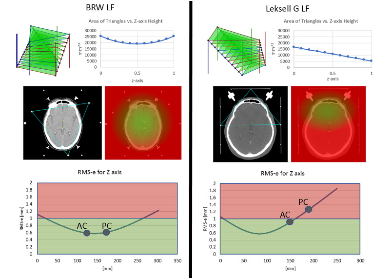
Figure 3. Depiction of the triangles formed by the fiducial points of the Brown-Roberts-Wells (BRW) localizer frame (LF) and Leksell G (LG) LF as well as the areas of the triangles over the normal to the z-axis (top images). For the BRW LF, the triangle’s area is nearly independent of the height of the axial computed tomography (CT) image. For the LG LF, the area varies according to the height of the CT image and is smaller for CT images that lie inferiorly. A smaller area correlates with a larger Root Mean Square error (RMS-e). Middle row of images are axial CT images showing the triangle formed by the diagonal rods and associated heat maps generated in MNPS that depicts an RMS-e for Z < (2*PixelSize) via green-shaded pixels computed using a barycentric representation of a linear property over the triangle and equation 36 in the Appendix. Note that the extent of the green heat map is much smaller for the LG LF than for the BRW LF. The pixel sizes for axial CT heat map images are 0.818 mm for BRW LF (bottom left) and LG LF (bottom right) using a 916x916 screen size matrix. Finally, RMS-e using Monte Carlo (MC) simulations for the BRW and LG LF are presented using three rods for the axial CT image (bottom row). In addition, the anterior commissure (AC) and posterior commissure (PC) are noted on the axial CT images and their associated locations are placed on the RMS-e curves.
BRW, Radionics CRW Stereotactic System, Integra LifeSciences Corporation, Plainsboro, New Jersey
Leksell G, Leksell Stereotactic Frame, Elekta, Stockholm, Sweden
Computed Tomography (CT)
MNPS - Mevis Stereotactic Planning System
Area of Triangles - Courtesy of Ross Anderson, PhD

