
Fig. 2.
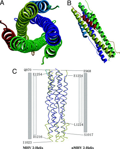
Overall views of the fusion core structure and superposition of nMHV (new construct for MHV fusion core) and MHV fusion core.A, top view of the MHV fusion core structure showing the 3-fold axis of the trimer. B, side view of the MHV fusion core structure showing the six-helix bundle. C, side view showing the superposition of nMHV fusion core (colored in blue) and MHV fusion core (colored in yellow). The columns at both sides of the map represent two HR1 and HR2 regions of nMHV and MHV fusion cores. The number at the end of these columns represents the end residues in the two structures.