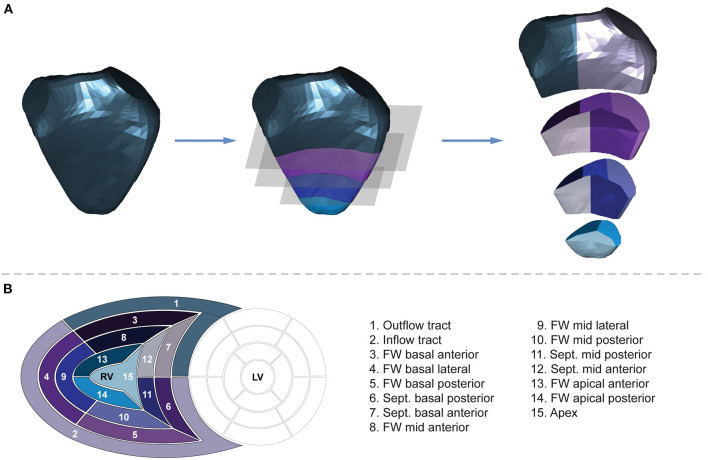
Figure 3.
Volumetric partitioning of the right ventricle. (A) Segmentation is performed on the end-diastolic mesh of each series to obtain 15 segments. First, the fraction of the mesh containing the inflow and outflow segments is separated by a horizontal slicing plane positioned at a predefined height along the longitudinal (i.e., vertical) axis. Then, the remainder of the mesh is trisected by two other horizontal planes at equidistant heights. Next, the horizontal slices are divided further. The inflow segment is separated from the outflow segment by a vertical slicing plane along the midpoint of the central vertices of the tricuspid and pulmonary annuli. Using vertically aligned standard planes, the septal and free wall portions of the horizontal slices are divided into further segments. The vertical slicing planes split the slices into three free wall and two septal segments on the basal and mid-levels and into two free wall and one apical segments on the apical level aiming for equal volume distribution among the segments within the given slice. See text for further details. The 3D right ventricular model is visualized from septal point of view. (B) The “bull's eye” plot and the nomenclature of the 15 newly generated right ventricular segments. FW, free wall; LV, left ventricle; RV, right ventricle; Sept., septum.

