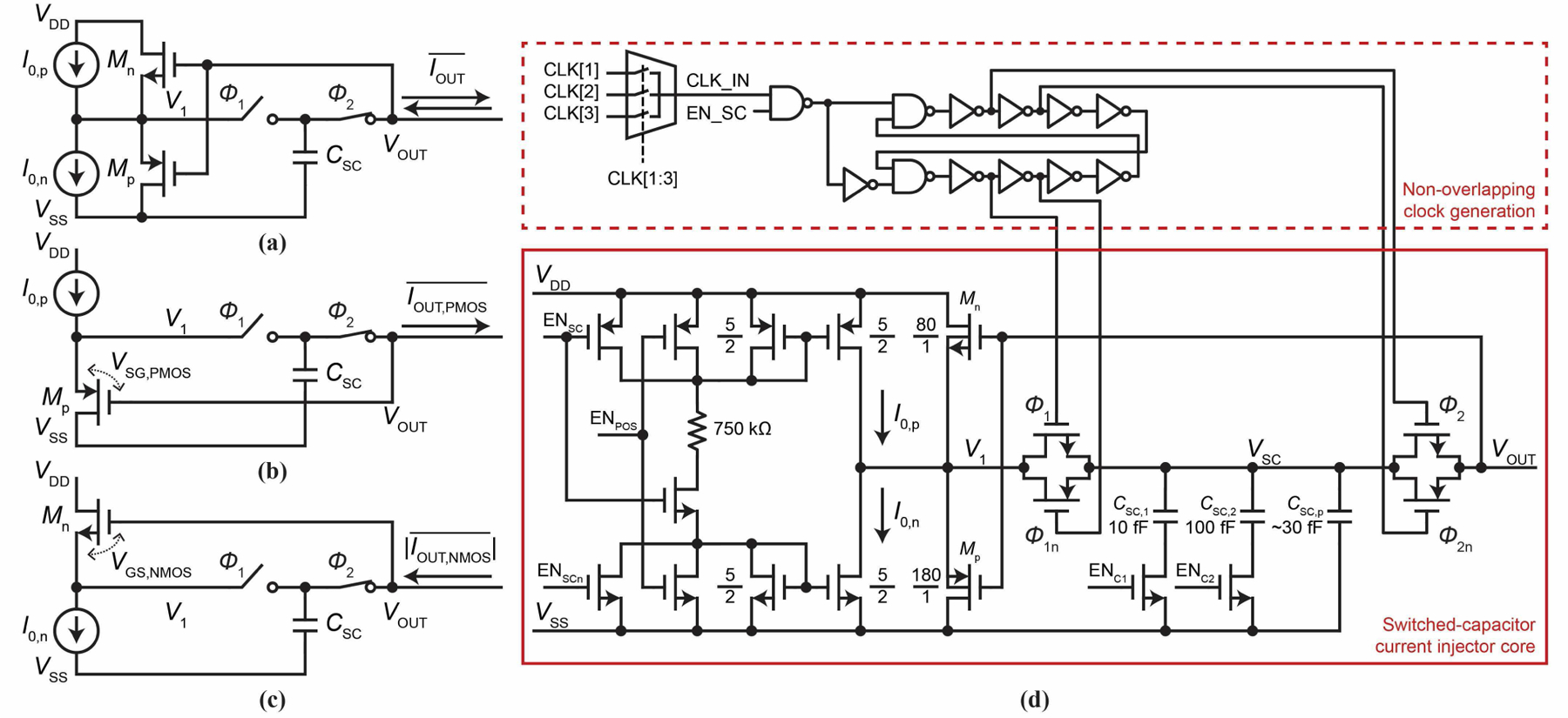
Fig. 7.

(a) The current injector we implement. (b) With I0,p on and I0,n off, part (a) is reduced to what is shown here, capable of positive current injection. (c) With I0,n on and I0,p off, part (a) is reduced to what is shown here, capable of negative current injection. (d) Transistor-level schematic of the current injector including the non-overlapping clock generation circuit. Control signals CLK[1:3], ENSC, ENPOS, ENC1, and ENC2 are controlled by the pixel’s transparent latch memory.
