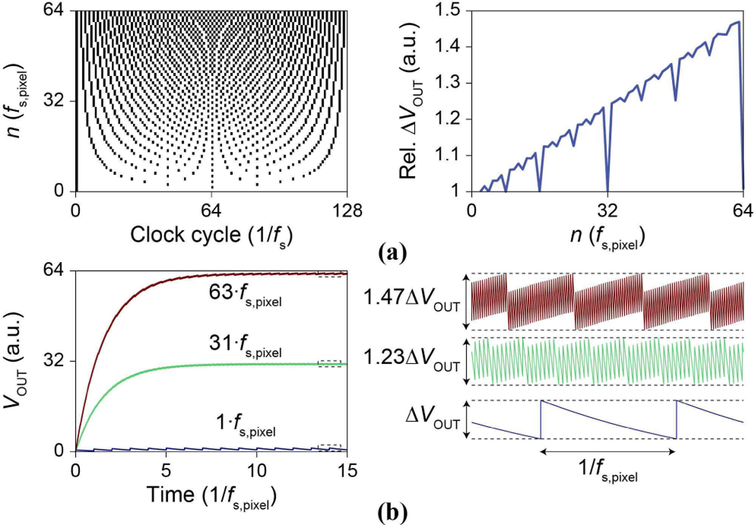
Fig. 8.

(a, left) pCC clocking scheme to synchronize the switched-capacitor current injector’s fsc to the multiplexer sampling at fs. Black indicates fsc high, white indicates fss low. The clock sequence is repeated after 128/fs . (right) ∆VOUT is increased due to the scheme. (b) Simulated VOUT traces for positive current injection for three different magnitudes and their steady state VOUT(t) ripple voltage.
