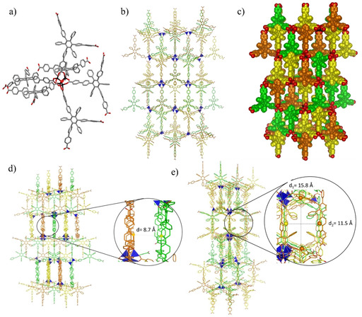
Figure 3.

Crystal structure of C‐MOF‐1 a) Capped sticks representation of a fragment of crystal structure of C‐MOF‐1 representing the octahedral arrangement of the C‐L‐1 linkers around the Zn cluster. Space group: Fdd2. b) Capped sticks and c) space‐fill representations of the packing view along the a axis showing three interpenetrating networks. d) View of the packing showing the distance between the networks and e) view along the ab face diagonal showing the cross section of the channels. The distances between the highlighted carbon atoms have been determined from the crystal structure taking into consideration the vdW radii. Colour code: C grey or coloured in orange, green and yellow for the two different networks; pink: B, blue: N, red: O, black or dark blue tetrahedron: Zn. H atoms were omitted for clarity.
