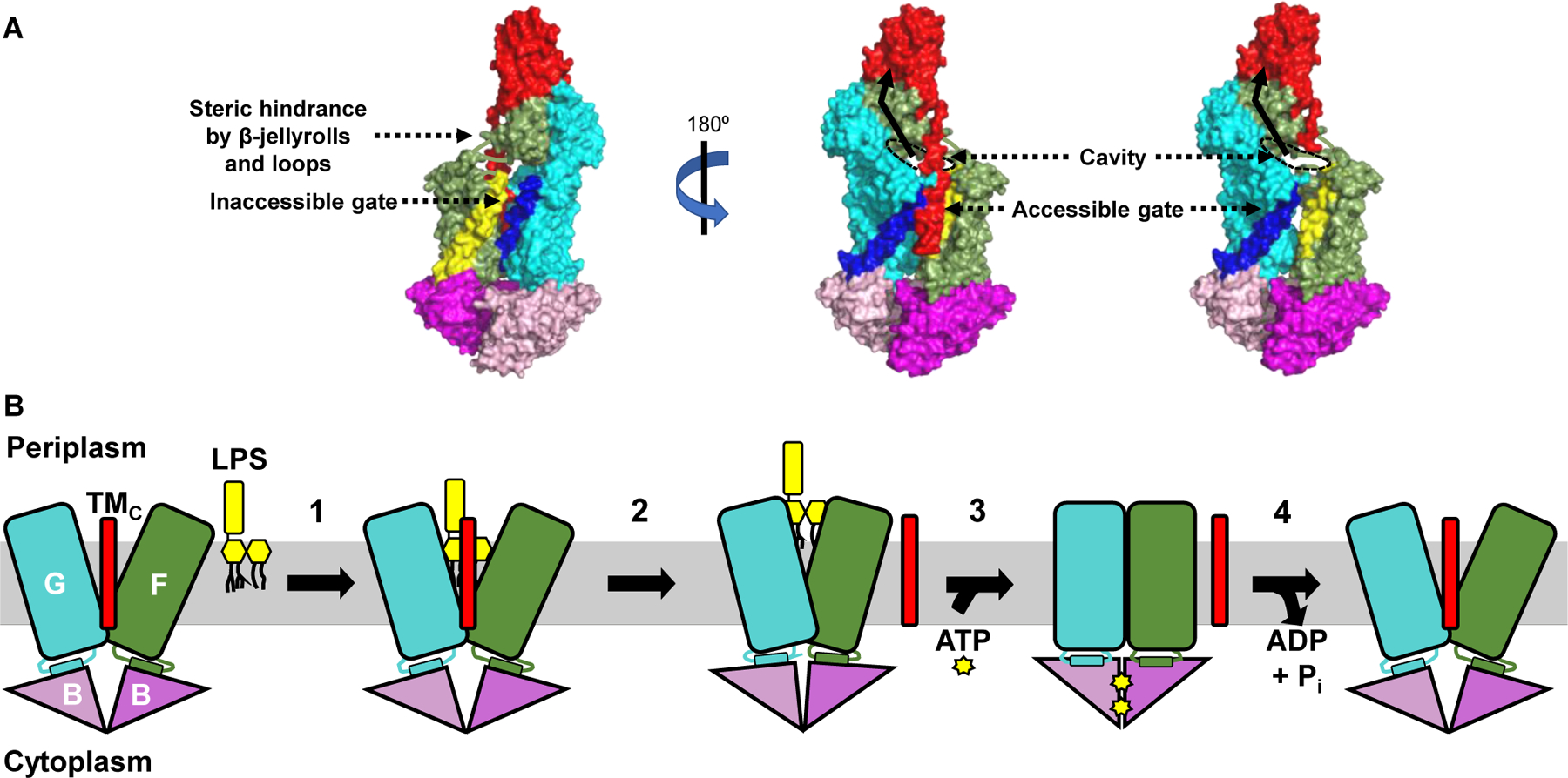
Figure 2: A model for LPS extraction from the IM by the LptB2FGC transporter.

A) Crystal structure (PDB ID: 6MJP) of LptB2FGC derived from Vibrio cholerae is shown with surface rendition. LPS is thought to enter the cavity formed by LptF and LptG through one gate of the transporter only, although two putative gates exist. The far-left image shows the first gate referenced in the text, with LptF TM1 in yellow and LptG TM5 in dark blue. Steric hindrance imposed by β-jellyroll domains of LptFG and the loops connecting the transmembrane and periplasmic regions of LptF/LptG is thought to impede entry of LPS through this gate. The central and far-right images show the second gate referenced in the text, with LptF TM5 in yellow, LptG TM1 in dark blue, and LptC in red. The TMC has been omitted from the far-right image to better show the substrate-binding cavity. The rim of the cavity that would be occupied by LPS is outlined with a black dashed oval, and the pathway LPS would take upon extraction from the IM is shown as a black solid arrow. B) The LptB2FGC complex is shown embedded in the IM but lacking the periplasmic β-jellyroll domains of LptCFG for clarity. Numbers indicate each step in the transport cycle. 1) LPS enters a cavity formed by LptFGC and makes initial, weak contacts with LptF and LptG. 2) The TMC is ejected from the cavity, which partially collapses to stabilize LPS through numerous contacts. The position of the TMC after its exit from the cavity is unknown. 3) Two ATP molecules bind the LptB dimer, causing its closure and facilitating complete collapse of the LptFG cavity. 4) ATP is hydrolyzed by the LptB dimer and ADP + Pi are released to reset the transporter.
