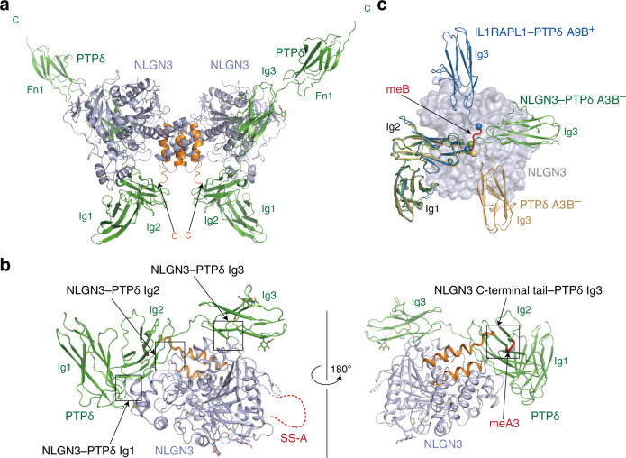
Fig. 3. Structure of the NLGN3–PTPδA3B– complex.
a Overall structure of the NLGN3 ECD–PTPδA3B– Ig1–Fn1 heterotetrameric complex. Two NLGN3 molecules are purple, except that their C-terminal regions containing two dimerization helices are orange. Two PTPδ molecules are colored in green. b Binding interfaces between NLGN3 and PTPδA3B–. The individual interfaces are indicated by boxes. The coloring scheme is the same as that in (a), except that the meA3 insertion in PTPδ is red. PTPδ Fn1 is not shown for clarity. c Superposition of the NLGN3-bound PTPδA3B– Ig1–Fn1 (green), apo-PTPδA3B– Ig1–Fn2 (PDB 4YFG; beige), and IL1RAPL1-bound PTPδA9B+ (PDB 4YH6; blue) using PTPδ Ig1–Ig2 as the reference. The bound NLGN3 is shown as a molecular surface colored in purple. The Fn domains of PTPδ or the bound IL1RAPL1 are not shown for clarity. The meB insertion is red. The Cα atoms of PTPδA9B+ Arg233 and Val238, which flank the meB insertion, are shown as spheres. Arg227 and Val228 of PTPδA3B– (equivalent to Arg233 and Val238 of PTPδA9B+, respectively) are also shown as spheres.

