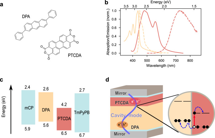
Fig. 1. Molecular system and device architecture.
a Molecular structures of 2,6-diphenylanthracene (DPA) and perylene-3,4,9,10-tetracarboxylic dianhydride (PTCDA). b The normalized absorption (solid line) and emission (dash line) spectra of DPA (yellow) and PTCDA (red) films. c Energy-level diagram of each molecule used in the study. To avoid any potential effect from the Ag mirrors, thin spacer layers was used. 10-nm mCP is chosen as the spacer between the bottom Ag mirror and DPA, and 15-nm TmPyPB between PTCDA and the top Ag mirror. The wide energy gap of the chosen materials enables them to act as an inert spacer, and neither energy nor electron transfer occurs between the spacers and active materials when in direct contact. d A typical structure of a Fabry–Pérot cavity in the study. From bottom to top: 30-nm Ag, 10-nm mCP, 163-nm DPA, 40-nm PTCDA, 15-nm TmPyPB, and 50-nm Ag. Schematics of the charge separation in the HJ are also shown.

