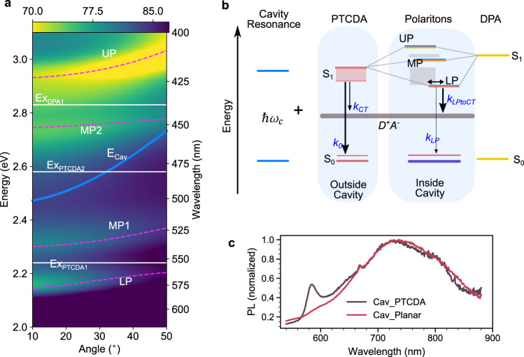
Fig. 2. Angle-resolved reflectivity and Jablonski diagram of the system in the strong coupling regime.
a Angle-resolved reflectivity (transverse electric mode) of a planar HJ cavity. The white solid lines indicate the excitons (ExPTCDA1, ExPTCDA2, and ExDPA1) and the blue line the cavity energy (ECav). The three excitons of PTCDA and DPA are strongly coupled to the mode of the cavity, leading to the formation of four polaritonic modes (LP, MP1, MP2, and UP), indicated by magenta dashed lines, which are a fit to a coupled oscillator model. b Jablonski diagram of the system. In the diagram, the two excitons of PTCDA are represented by a broad S1 band to simplify the diagram without affecting the underlying physics. The cavity photon () couples to both PTCDA and DPA and by doing so form the upper (UP), middle (MP), and lower polaritons (LP). The gray-color bands represent dark states. k0 and kCT are the decay rates of excited PTCDA to the ground state and charge-transfer state in the absence of a cavity, and kLP and kLPtoCT are the corresponding decay rates of LP to the ground state and charge-transfer states, respectively. The double arrow indicates the energy transfer between the exciton reservoir and LP. c Normalized emission spectra (excited at 475 nm) of the planar HJ cavity (Cav_Planar) and the reference cavity (Cav_PTCDA).

