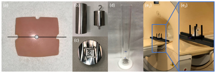
Figure 1.
Details of cartilage sample preparation and subsequent injurious impaction loading. (a) Top view of a representative osteochondral sample. Notches at the 3 and 9 o’clock positions indicate the mid-sagittal plane (black line), while the sample centre point is defined as the intersection of this mid-sagittal plane and its perpendicular along the notch at the 12 o’clock position (grey dot). (b) Weights of 1000 g (left) and 500 g (right) equipped with hook and 5 mm-tip to induce standardized injurious impaction. (c) Metallic sample plate with flat recess to fix cartilage samples during impaction by preventing lateral displacement. Seeming distortions are secondary to the milling process and room lights. (d) Cylindrical drop-tower device with metallic sample plate and indications of height. Impaction energy levels were regulated by adjustment of weight and height. Details of the assembled measurement framework at variable magnifications (blue boxes) within the scanner’s bore. The framework included support beams mounted on the MRI table (e1) and a transparent sample box (containing the cartilage samples, (e2)) for reproducible positioning of sample and coil (not shown).

