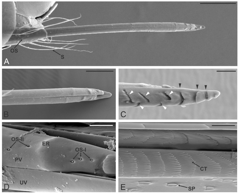
Figure 6.
Dryocosmus kuriphilus ovipositor. (A) General view of the true ovipositor, at the base a tuft of elongated setae (S) and the third pair of valves (the ovipositor sheath OS) are visible. (B,C) SEM micrographs of the paired valves (in (B)) and unpaired valve (in (C)). The latter presents transverse furrows as a single (black arrowheads) or double slots (white arrowheads). (D) Close-up view of the apical part of one of the paired valves (PV) still attached to the unpaired valve (UV): note the presence of a single furrow (black arrowhead) and the elevated region (ER). The area delimited by the furrow and the elevated region presents three ovipositor sensilla type I (OS-I), while a couple of ovipositor sensilla type II (OS-II) are observed just behind the ER. (E) SEM micrograph showing a detail of the internal organization of the paired valve: several ctenidia (CT) arranged in the parallel pattern can be observed, as well as some scale-like pegs (SP) positioned on the sliding surface of the valve. Bar scale: (A), 100 µm; (B), 50 µm; (C), 20 µm; (D), 10 µm; (E), 5 µm.

