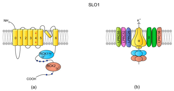
Figure 5.
SLO1 structure scheme. (a) A topology of the α subunit. Each α subunit consists of seven (0–6) TMs, where TM4 is a typical voltage-sensing domain (VSD). An extracellular loop between TM5 and TM6 forms the pore. The N-tail is located extracellularly but the C-end is a long tail containing the RCK1 (regulator of K+ conductance 1) and RKC2 domains [135]. The structural difference between SLO1 and SLO3 is that there are “Ca2+-bowl” structures within the RKC domains of SLO1, making the channel sensitive to [Ca2+]i. (b) In the tetrameric structure of the channel, the cytoplasmic C-termini creates a gating ring. According to the literature, SLO1 has five auxiliary subunits: one β subunit (with two transmembrane domains) and four Leucine-rich repeat-containing membrane proteins (LRRCs, also named γ subunits), LRRC26, LRCC52, LRRC55, and LRRC38, which modulate SLO1 sensitivity to Vm and [Ca2+]i (revised by Reference [144]). In murine testes and spermatozoa, two auxiliary subunits of the SLO3 channel have been identified: Lrrc52 and Lrrc26. Both of them are involved in the regulation of SLO3, and the expression of Lrrc52 is critically dependent on the presence of SLO3 [143]. The schemes are adapted from References [136,144].

