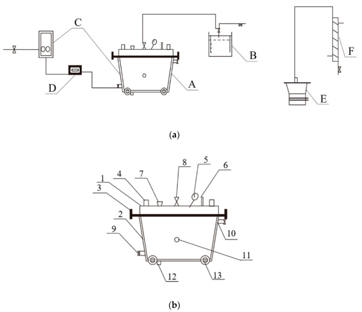
Figure 4.
Schematic diagram of the automatic brewing system and artificial pit. (a) The moveable automatic brewing system (A, artificial pit; B, gas-collection equipment; C, heating and cooling equipment using circulating water; D, temperature control equipment; E, distilling still for stewing grains and Zaopei; F, receiving device for alcohol condensation.); (b) the artificial pit [1, pit cover; 2, pit body (including an interlayer); 3, hold-down bolt; 4, handle; 5, manometer; 6, thermometer; 7, sampling filler; 8, bifurcated vent; 9, infall; 10, outlet; 11, temperature probe; 12, vent for sampling and draining; 13, pulley] (Image reprinted from ref. [23], Copyright 2021, with permission from John Wiley and Sons).

