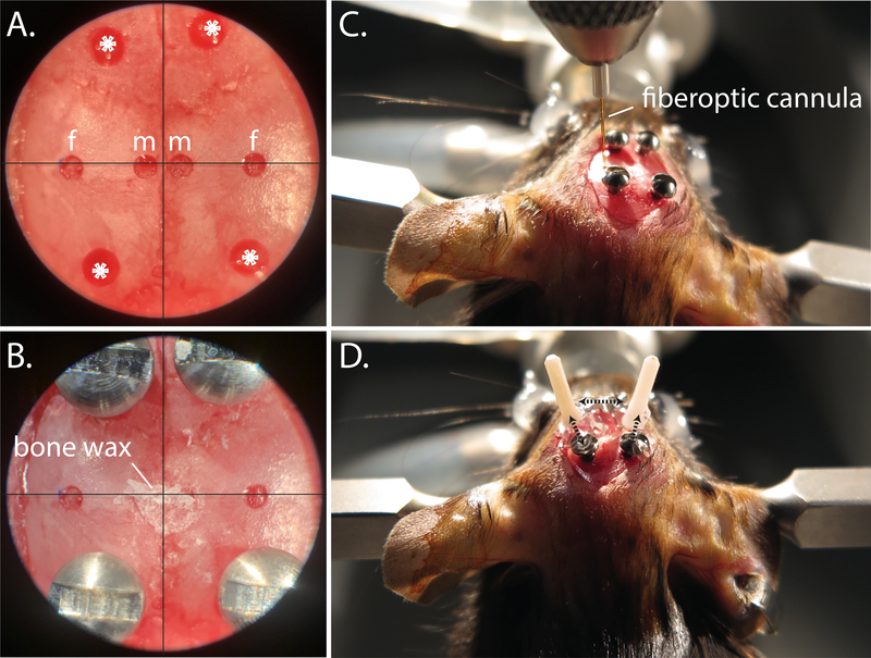
Figure 5: Fiberoptic implantation procedure.
A. Centering scope view of pilot holes for microinjection (m), fiberoptic (f), and anchor screws (*). B. Centering scope view of implanted anchor screws, and bone wax covered microinjection drill holes. C. Positioning the fiberoptic into place during angled implantation. D. Representative bilateral angled fiberoptic placement; dotted black arrows indicate areas where super glue is used to anchor the fiberoptic to the anchor screws and to the ipsilateral fiberoptic.

