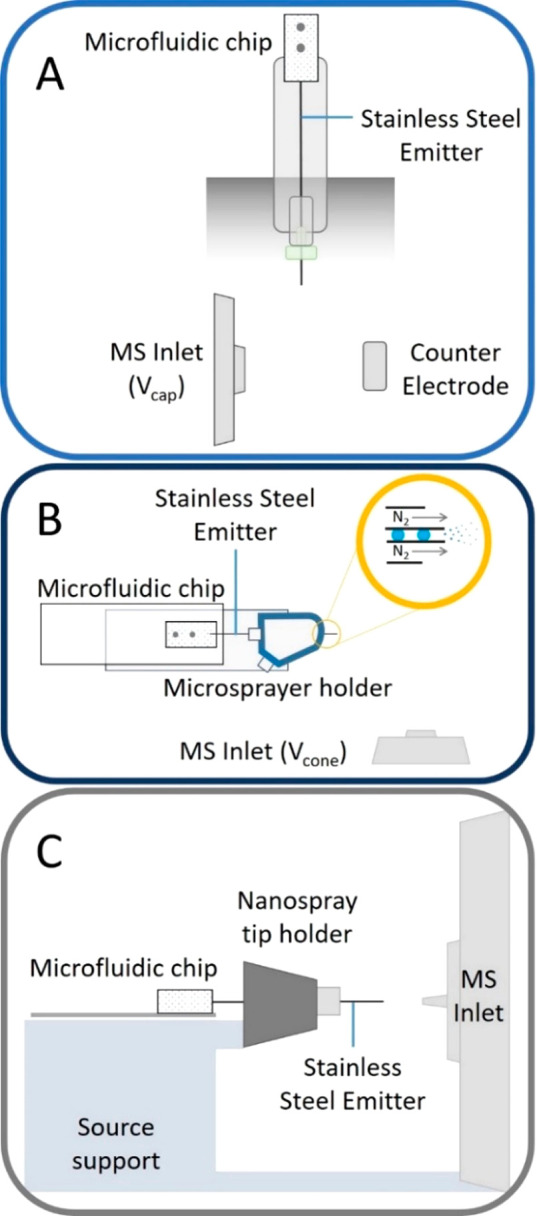
Figure 1.

(A) Schematic (side view) of the adaptation of a vertically mounted Agilent Nanospray ESI source to incorporate a microfluidic chip. Emitter is grounded and held ∼0.3 cm from a counter electrode held at ∼1.75 kV. Entire assembly is enclosed from the lab. (B) Schematic representation (top view) of the microfluidic chip interfaced to a Waters z-spray source by adapting a microspray assembly (source support not shown). Close up (yellow ringed inset) indicates coaxial gas flow around the stainless-steel emitter. Emitter is held at ∼2.8 kV and positioned 0.5 cm from the conical counter electrode which is the entrance to the mass spectrometer held at Vcone (∼54 V). (C) Schematic (side view) of the droplet microfluidic chip interfaced with the Thermo Fisher Q Exactive nESI source in which the stainless-steel emitter is inserted in the place of the nanospray tip and held in place with a conductive screw. Distance between the emitter and the entrance to the MS is 0.5 cm. These schematics are not to scale. Photographic representations indicating the scale and dimensions of the microfluidic chip within all 3 instrumental configurations can be found in the Supporting Information Figures S3, S4, and S6.
