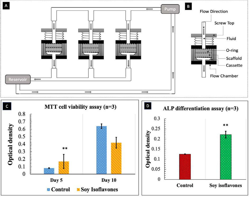
Fig. 8.
(A) Schematic diagram of perfusion flow bioreactor (B) Flow chamber and cassette diagram. Illustrated here is the design of the flow chamber in the flow perfusion culture system. The scaffold is press-fit into a custom-machined polycarbonate cassette. These cassettes are machined specifically to the diameter of the scaffolds used and can be made with different diameters for investigating scaffolds of varying dimensions. The cassette with scaffold is sealed in place by two neoprene O-rings above and below the cassette. This three-part assembly (cassette and two O-rings) is then held in place by a polycarbonate screwtop. Silicone tubing then connects each of these flow chambers to the pump and reservoir systems. (C) MTT assay (n=3) showing the effects of soy isoflavones loaded 3DP TCP bone tissue engineering scaffolds for in vitro osteoblast cell proliferation in a flow perfusion bioreactor at day 5 and 10. )[** denotes p-value <0.0001, statistically significant difference between control and test sample]. [Control: 3D TCP: 3D printed porous TCP scaffold] (D) ALP assay (n=3) showing the effects of soy isoflavones loaded 3DP TCP bone tissue engineering scaffolds for in vitro osteoblast cell differentiation in a flow perfusion bioreactor at day 10.[** denotes p-value <0.0001, statistically significant difference between control and test sample]. [Control: 3D TCP: 3D printed porous TCP scaffold]

